Remote data-monitoring systems have been widely used in nearly all manufacturing industries for many years and with several benefits. For example, these systems allow for the tracking, recording, and ongoing monitoring of data from different sensors — such as for temperature, pressure, flow, humidity, etc. — in a central control room of a plant.
Various sensors are placed within one or more of such devices and their readings (meaning the values of the temperature, humidity, or pressure, etc.) are recorded.
These sensor readings (the data) are sent to a remote monitoring station in one of two ways:
1. Through wires
2. Wirelessly
In some cases, a wired system is suitable and in others, a wireless one is more convenient. Both options have pros and cons, depending on the application.
In a wireless system, a transmitter is attached to a sensor that’s capable of transmitting sensor data. A remote receiver gets the data and can display and/or store it for later processing.
The system block diagram below provides a visual example. For this project, a sensor reads the temperature and sends it wirelessly to a remote location through an RF transmitter. At this location, an RF receiver receives this temperature data and displays it on an LCD.
The system is built using:
- Temperature sensors
- An Arduino microcontroller board
- An RF transmitter and receiver modules (ASK based)
- An LCD panel
System block diagram
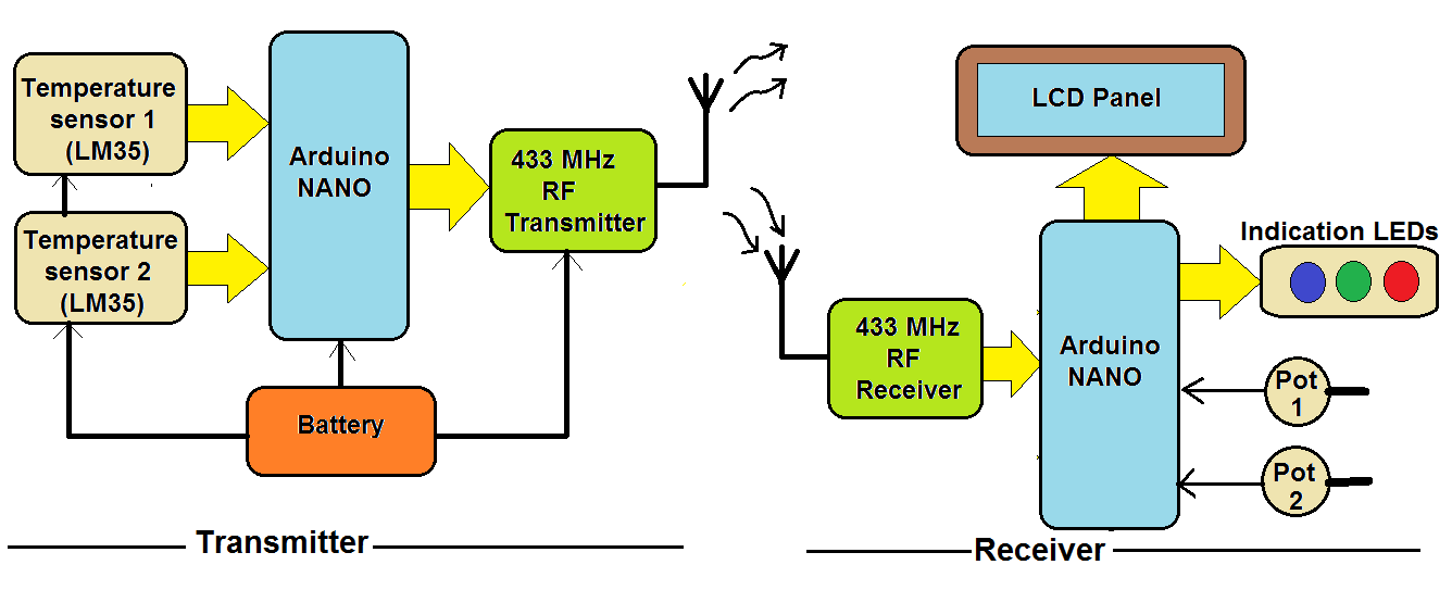
The complete system is divided into two distinct blocks:
1. The transmitter
2. The receiver
The transmitter consists of four items: the temperature sensor, a microcontroller, an RF transmitter, and a battery.
This is what we used for the project:
- A temperature sensor (LM35) to sense the surrounding temperature and provide analog output voltage, corresponding to the actual temperature.
- An Arduino nano board as a microcontroller that reads the temperature from the LM35 in analog voltage and provides this data to the RF transmitter.
- An ASK based RF transmitter module with 433 MHz carrier frequency to modulate and transmit the data to the receiver.
- A 9V battery is to provide power supply to the transmitter node.
- One LED that blinks to indicate the sensor node is active and is properly transmitting data.
The receiver consists of an RF receiver module, an LCD panel, indicating LEDs, potentiometers, and a microcontroller.
This is what we used:
- An ASK based RF receiver module with a 433MHz carrier frequency to de-modulate and receive the data transmitted by the sensor node of the RF TX module.
- An Arduino NANO board as a microcontroller to perform these tasks:
- Receive the data from the RF receiver module
- Display the temperature values on the LCD
- Provide indications on the LEDs
- Compare the actual temperature with the set temperature
- An LCD panel, which displays the actual temperature and the set temperature.
- Potentiometers to set the required temperature
Circuit diagram of the transmitter

As shown in this figure, there are only three major components in the circuit.
The temperature sensor LM35 has three pins: the Vcc, GND, and the output.
- The Vcc pin of both the LM35 sensors is connected to the Arduino board’s 5V output.
- The GND pins of the sensors are connected to the Arduino board’s ground pin.
- The output pins of both sensors are connected with the analog input pins A0 and A1, respectively.
The 433 MHz RF TX module has four interfacing pins: Vcc, GND, the data_in, and the antenna.
- The Vcc pin is connected to the Arduino board’s 5V output and the GND is connected with the common ground.
- The data_in pin is connected with the Arduino board’s digital pin D11.
- An antenna is formed by winding a 1mm @ 35cm long copper wire (a single core) that’s connected with the antenna pin.
- An LED is connected to digital pin D12 through a current-limiting resistor (as shown).
- A 9V battery is used to supply the Arduino board with power. The Arduino board’s VIN pin is connected with the battery.
The board will receive working voltage, generating a 5V supply from onboard the 7805 voltage-regulator chip, which is given to the LM35 and RF TX module.
Circuit diagram of the remote-data receiver
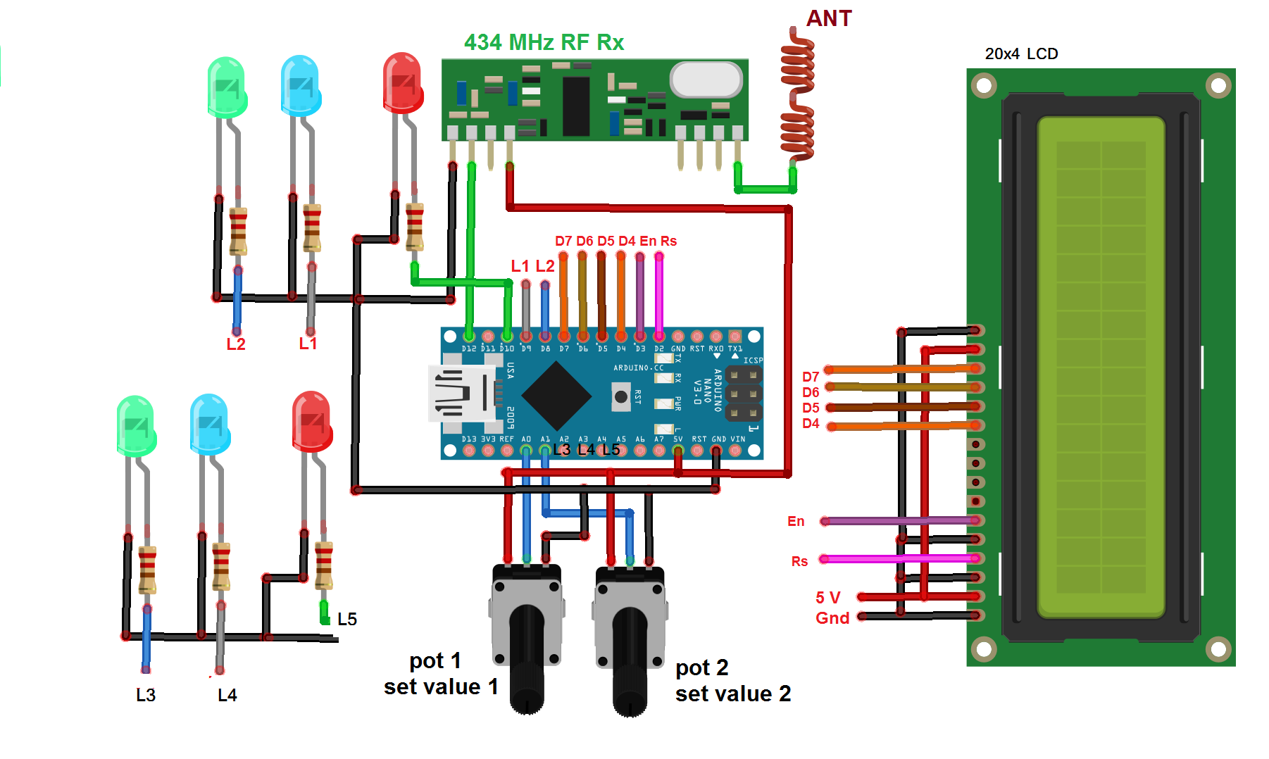
As shown in this figure, the receiver circuit only has three major components.
The 433 MHz RF RX module has four interfacing pins: Vcc, GND, data_out, and an antenna.
- The Vcc pin is connected with the Arduino board’s 5V output and the GND is connected with the common ground.
- The data_out pin is connected with the Arduino board’s digital pin D12. An antenna (same as on the transmitter side) is connected with the antenna pin.
- Two potentiometers are connected with the analog input pins A0 and A1 (as shown).
- Three LEDs (RED, GREEN, and BLUE) are connected with the digital pins D16, D17, and D18, respectively (actually, they’re A2, A3, and A4 but they’re used as digital pins) through the current-limiting resistors.
- Three more LEDs (RED, GREEN, and BLUE) are connected to the digital pins D8, D9, and D10, respectively, through current-limiting resistors.
- The LCD data pins D4-D7 are connected to the Arduino board’s digital pins D4-D7 and its control pins En and Rs are connected with digital pins D3 and D2.
- The Arduino board and complete receiver receive power supply from a laptop/desktop PC/central storage system computer through a USB cable. The Arduino board also logs data and communicates with the computer using the same USB cable.
Working and operation
The transmitter…
If I want to say the operation of a transmitter in a single line, I will say, “it will periodically sense temperature transmit them.”
The temperature sensor LM35 works on the principle of thermocouple. It generates an analog output voltage corresponding to the sensed temperature. It gives a calibrated output as 10mV / oC change (so, as the temperature changes 1oC, its output changes by 10mV).
As this analog output voltage is given to the analog input of the Arduino board, it will convert this voltage into a 10-bit digital value. This digital value is further converted into ASCII characters for the transmission.
Finally, Arduino gives this sensed temperature value to the RF TX module. The module will modulate this data using a 433MHz carrier and transmit it.
Remote data receiver…
The RF RX module receives data that’s transmitted by the transmitter. It de-modulates and gives it to the Arduino microcontroller. The microcontroller receives the data and extracts both temperature values. It displays both of the temperature values on the LCD as, “Actual temperature1: ” and “Actual temperature2. ”
Then, it reads the set temperature values through both potentiometers, which ranges from 20o to 80o C. These set temperature values are also displayed on the LCD as “Set temperature1: ” and “set temperature 2.”
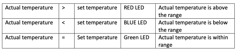
Finally, it compares the set temperature with the actual temperature (received from the transmitter) and indicates it on the LEDs, as per this table:
The transmitter program:
#include <VirtualWire.h>
const int led_pin = 13;
const int transmit_pin = 11;
char temp1[2], temp2[2];
void setup()
{
vw_set_tx_pin(transmit_pin);
vw_set_ptt_inverted(true); // Required for DR3100
vw_setup(2000); // Bits per sec
Serial.begin(9600);
pinMode(led_pin, OUTPUT);
}
void loop()
{
int t1,t2,tmp1,tmp2;
t1 = analogRead(A0);
t2 = analogRead(A1);
tmp1 = t1*500/1023;
tmp2 = t2*500/1023;
Serial.print(“temperature 1: “);
Serial.print(tmp1);
Serial.print(” *C\t”);
Serial.print(“Temperature 2: “);
Serial.print(tmp2);
Serial.println(” *C “);
digitalWrite(led_pin, HIGH); // Flash a light to show transmitting
itoa(tmp1,temp1,10);
itoa(tmp2,temp2,10);
vw_send((uint8_t *)temp1, 2);
vw_wait_tx(); // Wait until the whole message is gone
vw_send((uint8_t *)temp2, 2);
vw_wait_tx(); // Wait until the whole message is gone
delay(200);
digitalWrite(led_pin, LOW);
delay(4800);
}
The receiver program:
#include <VirtualWire.h>
#include <LiquidCrystal.h>
LiquidCrystal lcd(2,3,4,5,6,7);
const int led_pin = 13,green_led1=8,red_led1=10,blue_led1=9;
const int green_led2=16,red_led2=17,blue_led2=18;
const int receive_pin = 12;
int set_temp1,set_temp2,tmp1,tmp2;
void setup()
{
Serial.begin(9600); // Debugging only
Serial.println(“setup”);
vw_set_rx_pin(receive_pin);
vw_set_ptt_inverted(true); // Required for DR3100
vw_setup(2000); // Bits per sec
vw_rx_start(); // Start the receiver PLL running
lcd.begin(20, 4);
lcd.clear();
lcd.print(“Temp 1: “);
lcd.setCursor(0,1);
lcd.print(“set Temp 1: “);
lcd.setCursor(0,2);
lcd.print(“Temp 2: “);
lcd.setCursor(0,3);
lcd.print(“set Temp 2: “);
pinMode(led_pin, OUTPUT);
pinMode(green_led1, OUTPUT);
pinMode(red_led1, OUTPUT);
pinMode(blue_led1, OUTPUT);
pinMode(green_led2, OUTPUT);
pinMode(red_led2, OUTPUT);
pinMode(blue_led2, OUTPUT);
}
void loop()
{
uint8_t buf[VW_MAX_MESSAGE_LEN];
uint8_t buflen = VW_MAX_MESSAGE_LEN;
int i,j=0,k=0;
set_temp1 = analogRead(A0);
set_temp2 = analogRead(A1);
set_temp1 = map(set_temp1,0,1023,20,80);
set_temp2 = map(set_temp2,0,1023,20,80);
lcd.setCursor(11,1);
lcd.print(set_temp1);
lcd.print(” *C”);
lcd.setCursor(11,3);
lcd.print(set_temp2);
lcd.print(” *C”);
if (vw_get_message(buf, &buflen)) // Non-blocking
{
digitalWrite(led_pin, HIGH);
Serial.print(“Temperature 1: “);
lcd.setCursor(8,0);
for (i = 0; i < 2; i++)
{
Serial.print(buf[i]-48);
lcd.print(buf[i]-48);
lcd.print(” *C”);
}
Serial.println(” deg C”);
Serial.print(“Temperature 2: “);
lcd.setCursor(8,2);
for (i = 2; i < 4; i++)
{
Serial.print(buf[i]-48);
lcd.print(buf[i]-48);
lcd.print(” *C”);
}
Serial.println(” deg C”);
}
digitalWrite(led_pin, LOW);
tmp1 = (buf[0]-48)*10 + (buf[1]-48)*1;
tmp2 = (buf[2]-48)*10 + (buf[3]-48)*1;
led_indications();
}
void led_indications()
{
if(tmp1>set_temp1+5)
{
digitalWrite(red_led1,HIGH);
digitalWrite(blue_led1,LOW);
digitalWrite(green_led1,LOW);
}
else if(tmp1<set_temp1-5)
{
digitalWrite(red_led1,LOW);
digitalWrite(blue_led1,HIGH);
digitalWrite(green_led1,LOW);
}
else
{
digitalWrite(red_led1,LOW);
digitalWrite(blue_led1,LOW);
digitalWrite(green_led1,HIGH);
}
if(tmp2>set_temp2+5)
{
digitalWrite(red_led2,HIGH);
digitalWrite(blue_led2,LOW);
digitalWrite(green_led2,LOW);
}
else if(tmp2<set_temp2-5)
{
digitalWrite(red_led2,LOW);
digitalWrite(blue_led2,HIGH);
digitalWrite(green_led2,LOW);
}
else
{
digitalWrite(red_led2,LOW);
digitalWrite(blue_led2,LOW);
digitalWrite(green_led2,HIGH);
}
}
Filed Under: Arduino, Microcontroller Projects

Questions related to this article?
👉Ask and discuss on EDAboard.com and Electro-Tech-Online.com forums.
Tell Us What You Think!!
You must be logged in to post a comment.