Nowadays all consumer electronics appliances or equipments has remote control facility for easy and convenient operation. Normally pedestal fan has mechanical switch to control the speed and oscillation. Buying a remote controlled fan slightly increases the cost of the fan. Presented here a circuit to convert your ordinary pedestal fan into a remote control pedestal fan without using any microcontroller. This circuit is designed for pedestal fan motor (Universal Motor) with multiple tappings for speed control. Moreover, this circuit can be used for all type of pedestal and table fan with small alteration in the circuit.
CIRCUIT AND WORKING
The circuit is build around encoder and decoder IC’s HT12D and HT12E along with 433MHz RF transmitter and receiver module. When any key is pressed, the data is converted serially by the encoder and it transmitted by the RF transmitter module. The RF receiver module receives the serial transmitted data and it decodes by the decoder and the corresponding data pin was activated. The relay connected to the data pin was energized thereby the tappings was connected to the supply through the ‘NO’ contact.
TRANSMITTER
The transmitter circuit was shown below. The circuit is powered by a 9V battery. The IC 78L05 (U1) converts 9V into regulated 5V for encoder IC and the transmitter module for proper operation. When any data button (S3-S6) is pressed, the corresponding data pin was grounded at the same time the transmission enable (TE) was pulled to ground through the diode connected in series with the buttons. Since the TE pin was grounded while pressing the buttons, the data was transmitted during button debouncing time only. This saves power when operating from battery powered circuits.
The DIP switch (S7) sets the 8 bit address code for the transmitting data. Thus the data along with the address was converted serially and it transmitted through the 433MHz RF transmitter module. The button S2 is for resetting the all relays in the receiver.
HT12E
HT12E is a CMOS Large Scale Integration(LSI) IC capable of encoding information 12 bits of parallel data into serial data. These 12 bit of parallel data was divided into 8 address bits and 4 data bits. Each address or data input can be set to HIGH or LOW. It has built-in oscillator which requires a small value of external resistor and it is able to operate in wide range of voltages from 2.4V to 12V.
RECEIVER
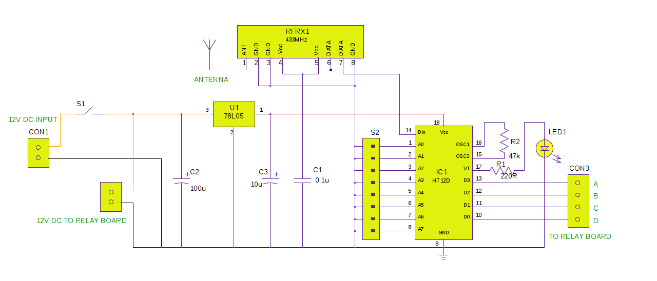
The circuit diagram of receiver was shown below. It is powered by an external 12V supply. It is converted into 5V by 78L05 voltage regulator U1 for decoder IC and the receiver module for proper operation.The serial data from the RF receiver module was fed into the decoder IC HT12D. The DIP switch (S2) sets the 8 bit address for the decoder. This address must match with the transmitter address to decode the data. The decoder check the address bits three times and if it matches with the transmitter, the decoder decodes the data and latches the DATA pins.
The Valid Transmission (VT) pin goes high to indicate that a valid transmission was occurred. The DATA pins stays latched until new data arrives.
HT12D
HT12D is a CMOS Large Scale Integration(LSI) IC capable of decoding information that consists of 8 address bits and 4 data bits. These decoders are paired with the encoders to exchange the data. The decoder compares the serial input data three times continuously with their local addresses. If no error found or both the addresses are matched, the input data are decoded and it transferred to output. The VT pin goes HIGH to indicate a valid transmission.
RELAY BOARD
The 4 channel relay board can be used for this circuit which is readily available in the market. Here two different voltage is required for the board. 5V is for opto-isolated driver circuit and 12V for energizing the relay.

Fig. 1: Typical Image of Relay Board
NOTE:
This circuit is designed for pedestal fan which has multi-tapped universal motor for speed control and independent synchronous motor for oscillation. If the fan doesn’t have sync motor for oscillation, neglect the relay connected to the data pin of the decoder.

Fig. 2: Circuit Diagram of RF Remote Control for Pedestal Fan
12V SMPS power supply is recommended for the receiver circuit since it is easily fits in the fan’s housing due to its light weight and compact size.
Circuit Diagrams
Filed Under: Electronic Projects

Questions related to this article?
👉Ask and discuss on EDAboard.com and Electro-Tech-Online.com forums.
Tell Us What You Think!!
You must be logged in to post a comment.