The project utilizes DHT sensor to keep a track of ambient temperature and humidity and a moisture sensor to record soil moisture. The RTC DS1307 is used keep track of real time so that the moisture rating could be logged and relayed over fixed interval of time in a real-time fashion. The project sends out the real-time alert of inappropriate moisture levels through SMS using a GSM/GPRS modem to a registered mobile number of the farmer or caretaker. The system is able to automatic control a water pump which can be switched on through SMS in response to the real-time alert. Once the water pump is switched on through SMS it automatically switches off after the appropriate moisture level is attained.

Fig.1 : Prototype of Arduino based Soil Moisture Detector and Mobile operated Automatic Water Pump Controller
The farmer or caretaker can also switch off the water pump in between by sending an SMS or manually operating the project interface. The data log of message alerts can also be cleared through the project interface. The human interface attached to the project consists of a 16X2 LCD display which runs the mobile registration process on the start of the system and allows mobile registration update and display of current soil health readings when prompted. The input to the system is fed through a numeric keypad and all the instructions feed to the system are also numeric codes.
The project has the following execution cycle-:
1) As the system is powered on, it prompts the user for mobile number registration by displaying initial messages on the LCD display. The user has to press “*”, enter his mobile number and press “#” to complete the mobile number registration. If the user has already registered his mobile number on the device, he can cancel the process by pressing “#” without entering the mobile number.
2) The registered mobile number is saved to the internal memory of the Arduino Mega.
3) After the mobile number registration, the Arduino board fetch the real time from RTC module, humidity, and temperature using DHT11 sensor and moisture level through the moisture sensor and start displaying all the readings on LCD display.
4) Once the system is initialized, the user needs to set the time interval for SMS alerts of the moisture level. The system can accept any time duration as required by the user for SMS alerts of moisture level.
5) When the system will find the moisture level below the set level, warning SMS alert is sent to the registered mobile number.
6) The user can respond to the warning SMS alert by replying back an SMS “ON MOTOR” which will switch ON the water pump for a duration until the moisture level increases to the set level. The water pump automatically switches OFF once the required moisture level is attained.
7) The user can also turn OFF the water pump manually if finds that suitable.
Once the project is initialized after mobile number registration and it starts displaying moisture, date-time, and temperature and humidity readings, it is ready to accept the following numeric instruction codes.
• Run time phone number update: When the device starts it always prompts the user to register the phone number. The phone number can also be updated during the run time of the project which can be initiated by pressing “0”. Thereafter, the user has to enter the new mobile number for renewing registration and press “#” to complete the registration process.
• Deleting SMS log: By pressing ‘*’ during runtime the user can delete all the messages saved to the SIM card inserted in GSM/GPRS module.
• Setting time interval for SMS alerts: By pressing hash ‘#’ user can initiate setting the time interval in seconds and pressing ’#’ again saves the entered time interval to the internal memory of the board.
• Manual Moisture Level Check: User can check the moisture level manually by pressing ‘1’ on the keypad.
• Registered Mobile Number Check: User can check the registered mobile number pressing ‘2’ on the keypad.
• Time Interval Check: User can check the time delay set to wait for the response by pressing ‘3’ on the keypad.
Components Required
• Arduino Mega2560
• GSM/GPRS Module SIM900
• RTC module-DC1307
• Moisture sensor with analoge output.
• DHT11 humidity and temperature sensor
• 16×2 LCD
• Capacitor 25v, 4700uF
• Transformer 18-0, 2Amp -1pc
• 1N4007 diode -4pcs
• 12v Relay-1pc
• BC 547 transistor-1pc
• 1K ohm resisters -3pcs
• 4×3 keypad-1pc
• Voltage regulator -7805 and 7812
• LED -5mm RED- 2
• Wire to carry 2A, 230v AC

Circuit Connections
As is clear from the block diagram the heart of the project is Arduino Mega board and all other circuit sections are connected to it. There are following sections of the project circuit -:
1) Power Supply Regulator
2) Relay Circuit as Power Switching Unit.
3) RTC Module DS1307
4) LCD Display
5) 4×3 Keypad
6) GSM/GPRS Module
7) DHT11 sensor
The Arduino Board is the programmable Unit controlling the entire functionality of the project and every module is interfaced to it. The circuit is connected in the following manner -:
1) Power Supply: While the water pump will need AC supply, the project circuit needs 12V and 5V DC supply. The 12V supply is provided via 7812 voltage regulator and supplied to the 12V relay and 7805 voltage regulator. The other components need a 5V DC supply which is provided through 7805 voltage regulator that is converting the input 12V supply to 5V DC.
2) Relay Circuit: The water pump is connected to the circuit through a 12V relay. The relay is connected to the pin 24 of Arduino Mega board and have a BC547 transistor circuit of a common emitter configuration for interfacing with the board.
3) DHT11 connection: The data pin of temperature and humidity sensor DHT11 is connected to pin 10 of the Arduino Mega and ground and VCC connected to the relevant pins.
4) RTC Module: DS1307 RTC module is used in the circuit. The 5V DC supply and ground to the RTC module are provided by the 7805 voltage regulator. The SDA and SCL pins of the RTC are connected to the SDA and SCL pins of Arduino Board respectively. Learn more about RTC and its interfacing with Arduino UNO. The standard library of Arduino for RTC is used in the program code to run RTC specific project code.
5) GSM/GPRS MODULE: Here Arduino Mega is using TX1 and RX1 from its three USART ports. Vcc and ground are provided with the external power supply of 12v, 2Amp, and common ground. The TX terminal of GSM module is connected to the pin 19 (RX1) of Arduino Mega and its Rx terminal is connected to the pin 18 (TX1) of Arduino mega. Read more.

Fig. 3: Table listing circuit connections between Arduino Uno and Character LCD
The standard code library for interfacing Arduino is used in the project to program LCD with the Arduino board. Learn more about LCD interfacing with ARDUINO
4×3 Keypad: This is a numeric keypad having 12 input buttons arranged in 3 columns and 4 rows. In the keypad, 4 wires are used as ROWS and three wires are used as COLUMNS. The wire number can be count from the left-hand side to the right-hand side. The row and column wires are interfaced to the Arduino pins in the following manner.
How the Circuit Works
The circuit works in following stages -:
1) Initialization of the circuit
As the circuit is switched on Arduino loads the imported libraries of LCD display, DHT library, EEPROM library, keypad library and RTC library. First Initial messages are flashed on the display screen prompting to complete mobile number registration. The user needs to enter his phone number and press “#” to complete the registration process. After that the current date and time are fetched from the RTC and humidity and temperature readings are fetched from the DHT11 sensor and they are displayed on the LCD screen.
2) After phone number registration, the user is prompted to enter a time interval for SMS alert of real-time soil health and the system goes into the operating mode. The device starts sending SMS containing details like moisture level, ambient temperature, and relative humidity by the interval set by the user.
3) Low moisture level detection: System checks the moisture level on a polling basis and whenever the system detects low-level moisture, it sends a warning SMS to the user. The device waits till the user switches ON the water pump or until the moisture level resumes to its best level.
4) SENDING SMS: When the user gets the warning SMS, he has to reply back by sending SMS “ON MOTOR” to the device in order to switch the water pump ON and he can send “OFF MOTOR” SMS to switch the water pump OFF.
Programming Guide
The code utilizes standard libraries of the Arduino. Therefore, first of all, predefined libraries for LCD display, DHT sensor, EEPROM library, keypad library and RTC library are imported in the code. An LCD object is instantiated and mapped to pins 13, 12, 6, 5, 4 and 3 of the Arduino. An object of RTC type and an object dht of DHT type is declared. For keypad interfacing, two constants representing a number of rows and columns of the keypad are defined and used in the declaration of arrays for representing individual keys of the keypad. The keys are mapped to Arduino pins as mentioned in the table given above. The variables to hold values of temperature, relative humidity, and moisture level are declared. A string object is declared to hold SMS text and a flag is set to check the status of SMS alert. A ‘relay’ variable is declared and assigned to the pin 24 where relay has been connected. The numeric representation of keys is assigned by a two-dimensional array and variables to hold time and phone number are declared. A keypad object is declared and assigned key map.

Fig. 4: Screenshot of initialization in Arduino Code for Soil Moisture Detector and Mobile operated Automatic Water Pump Controller
The baud rate for the Arduino and the GSM module is set to 9600 bits per second. The pinMode() and digitalWrite() functions are used to set the input/output mode and pin status of the Arduino IC pins. The LCD object is initialized and initial messages are flashed on the display screen. The RTC is tested to fetch current date and time.

Fig. 5: Screenshot of Setup Function in Arduino Code for Soil Moisture Detector and Mobile operated Automatic Water Pump Controller
A loop() function is called where the key pressed by the user is detected and messages are flashed on the LCD screen prompting user to register mobile number. The registered mobile number is saved using saveNUM() function and the display screen is cleared by detecting the “#” pressed.

Fig. 6: Screenshot of Loop Function in Arduino Code for Soil Moisture Detector and Mobile operated Automatic Water Pump Controller
A function moistureAlertSMS() is declared where the analog reading from moisture sensor is fetched and the reading is saved as an SMS in proper format to GMS module.

Fig. 7: Screenshot of Moisture Alert SMS Function in Arduino Code for Soil Moisture Detector and Mobile operated Automatic Water Pump Controller
A lowalertSMS() function is called where the mobile number is fetched from the EEPROM and an SMS for low moisture level is pushed to the GSM module.

Fig. 8: Screenshot of LowAlertSMS Function in Arduino Code for Soil Moisture Detector and Mobile operated Automatic Water Pump Controller
A processSMS() function is called which detects the reply SMS and operates the relay to switch the water pump on or off. The current status of the motor pump is displayed on the LCD screen simultaneously.

Fig. 9: Screenshot of ProcessSMS Function in Arduino Code for Soil Moisture Detector and Mobile operated Automatic Water Pump Controller
Finally a function matchTIM() is declared where the time interval to send the SMS alert is set and the SMS is pushed out according to the set time interval. The message “TIME MATCHED” is displayed on the LCD screen at the instant SMS is sent to the registered mobile number.

Fig. 10: Screenshot of matchTIM Function in Arduino Code for Soil Moisture Detector and Mobile operated Automatic Water Pump Controller
Project Source Code
###
#include<dht.h> #include <Wire.h> #include<EEPROM.h> #include <RTClib.h> #include <LiquidCrystal.h> #include <Keypad.h> #include <SoftwareSerial.h> LiquidCrystal lcd(13, 12, 6, 5, 4, 3);// Pins used for RS,E,D4,D5,D6,D7 RTC_DS1307 RTC; dht DHT; //dht for DHT sensor const byte ROWS = 4; //for four rows const byte COLS = 3; //for three columns byte rowPins[ROWS] = {A8, A9, A10,A11}; //connect to the row pinouts of the keypad contains four pins byte colPins[COLS] = {A12, A13, A14}; //connect to the column pinouts of the keypad contains three pins int value,pos=0,moist,newTime,prevTime,a=0,temp,hoursE=0,delayTIM; #define dht_dpin 10 //Pin defined for DHT11 sensor at pin number 10 of arduino Mega String msg = String(""); // String buffer for the GPRS shield message int SmsContentFlag = 0;//Set to 1 when the next GSM/GPRS modem contains a SMS message int relay=24;//Pin declare for relay control at pin number 24 of arduino mega char keys[ROWS][COLS] = { {'1','2','3'}, {'4','5','6'}, {'7','8','9'}, {'*','0','#'} }; int lastMinute,i=0,count=0,num[10],phno[10],HOUR=0,MINUT=0,SECOND=0;//Variable to store phone number Keypad keypad = Keypad( makeKeymap(keys), rowPins, colPins, ROWS, COLS ); void setup() { Serial1.begin(9600); // Setting the baud rate of GSM Module Serial.begin(9600); // Setting the baud rate of Serial Monitor (Arduino) pinMode( relay, OUTPUT ); digitalWrite( relay, LOW ); Serial.println( "AT+CMGF=1" ); delay(200); Wire.begin(); RTC.begin(); lcd.begin(16,2); lcd.setCursor(0,0); lcd.print("Engineers Garage"); lcd.setCursor(0,1); lcd.print("MOISTURE DETECT "); delay(3000); if(!RTC.isrunning()) { RTC.adjust(DateTime(__DATE__,__TIME__)); } digitalWrite(13, LOW); lcd.setCursor(0,0); lcd.print("ENTER MOBILE NO."); lcd.setCursor(0,1); lcd.print(" YES* NO# "); DateTime now = RTC.now(); prevTime= now.minute(); //lcd.print(" "); } void loop() { char key = keypad.getKey(); while(pos==0){ char key = keypad.getKey(); if(key=='*' && pos==0){ lcd.setCursor(0,0); lcd.print("ENTER MOBILE NO."); lcd.setCursor(0,1); lcd.print(" "); saveNUM(); } if(key=='#' && pos==0){ //sendSMS(); lcd.clear(); pos=2; break; } } moist=analogRead(A0); if(moist>=950){ a=0; // while(1){ lowAlertSMS(); lcd.setCursor(0,0); lcd.print(" SOIL MOISTURE "); lcd.setCursor(0,1); lcd.print(" LOW DETECTED "); delay(1000); while(1){ char SerialInByte; moist=analogRead(A0); if(Serial1.available()) { SerialInByte = (unsigned char)Serial1.read(); delay(5); if( SerialInByte == 13 ){ ProcessGprsMsg(); Serial.println( "*** SMS Received ***" ); } if( SerialInByte == 10 ){ } else { msg += String(SerialInByte); } } if(a==1 ||moist <=950){ digitalWrite( relay, LOW ); lcd.setCursor(0,0); lcd.print(" MOTOR IS IN "); lcd.setCursor(0,1); lcd.print(" OFF CONDITION "); lcd.clear(); break; } } } if(key=='1'){ moistureDETECT(); } if(key=='2'){ detectNUM(); } if(key=='0'){ lcd.setCursor(0,0); lcd.print("ENTER MOBILE NO."); lcd.setCursor(0,1); lcd.print(" "); saveNUM(); } if(key=='#'){ lcd.clear(); timerSET(); } if(key=='3'){ lcd.clear(); value = EEPROM.read(11); lcd.setCursor(0,0); lcd.print(" TIME SET FOR "); lcd.setCursor(0,1); lcd.print(" EVERY HOUR "); lcd.setCursor(8,1); lcd.print(value); delay(3000); delay(3000); } if(key=='*'){ lcd.clear(); for(int i=1;i<41;i++){ Serial1.print( "AT+CMGD=" ); Serial1.println(i); lcd.setCursor(0,0); lcd.print(" DELETING SIM "); lcd.setCursor(5,1); lcd.print("MSGS"); lcd.setCursor(10,1); lcd.print(i); delay(500); } } delay(1000); lcd.setCursor(8,0); lcd.print(" "); lcd.setCursor(10,1); lcd.print(" "); DHT.read11(dht_dpin); DateTime now = RTC.now(); lcd.setCursor(0,0); printDigits2(HOUR=now.hour()); lcd.print(":"); printDigits2(MINUT=now.minute()); lcd.print(":"); newTime = now.minute(); printDigits2(SECOND=now.second()); lcd.setCursor(0,1); lcd.print(now.day(),DEC); lcd.print("/"); lcd.print(now.month(),DEC); lcd.print("/"); lcd.print(now.year(),DEC); lcd.setCursor(0,1); lcd.print(now.day(),DEC); lcd.print("/"); lcd.print(now.month(),DEC); lcd.print("/"); lcd.print(now.year(),DEC); lcd.setCursor(9,0); lcd.print("H:"); lcd.print(DHT.humidity); lcd.setCursor(15,0); lcd.print("%"); lcd.setCursor(11,1); lcd.print("T:"); lcd.print(DHT.temperature); lcd.print((char)223); lcd.setCursor(15,1); lcd.print("C"); matchTIM(); } void saveNUM(){ while(1){ char key = keypad.getKey(); if (key){ //Serial.println(key); phno[i]=key; num[i]= phno[i]-48; lcd.setCursor(13,1); lcd.print(" "); lcd.setCursor(i+3,1); lcd.print(num[i]); count++; i++; delay(500); if(key=='#' && count==11){ for(int j=0;j<11;j++){ lcd.setCursor(0,0); lcd.print("***** WAIT *****"); EEPROM.write(j, num[j]); delay(500); } lcd.setCursor(0,0); lcd.print(" NUMBER SAVED "); lcd.setCursor(0,1); lcd.print("***************"); lcd.clear(); pos=1; break; } } } } void printDigits2(int digits) //this void function is really useful; it adds a "0" to the beginning of the number, so that 5 minutes is displayed as "00:05:00", rather than "00:5 :00" { if(digits < 10) { lcd.print("0"); lcd.print(digits); } else { lcd.print(digits); } } void printDigits3(int digits) //this void function is really useful; it adds a "0" to the beginning of the number, so that 5 minutes is displayed as "00:05:00", rather than "00:5 :00" { if(digits < 1000) { lcd.print(" "); lcd.print(digits); } else { lcd.print(digits); } } void moistureDETECT(){ lcd.clear(); lcd.setCursor(0,0); lcd.print("Moisture Content"); while(1){ char key = keypad.getKey(); moist=analogRead(A0); lcd.setCursor(6,1); printDigits3(moist); if(key=='*'){ lcd.clear(); break; } } } void detectNUM(){ lcd.clear(); lcd.setCursor(0,0); lcd.print(" OWNER's NO. "); for(int j=0;j<11;j++){ value = EEPROM.read(j); lcd.setCursor(j+3,1); lcd.print(value); lcd.setCursor(13,1); lcd.print(" "); delay(300); } while(1){ char key = keypad.getKey(); if(key=='*'){ lcd.clear(); break; } } } void timerSET(){ int k=0; lcd.setCursor(0,0); lcd.print("SET TIME FOR: "); while(1){ char key = keypad.getKey(); lcd.setCursor(13,0); while(pos==2){ DateTime now = RTC.now(); char key = keypad.getKey(); if(key){ lcd.print(key); delayTIM=key-48; prevTime=now.minute(); EEPROM.write(12, prevTime); delay(500); pos=3; break; } } if(pos==3 && key=='#'){ EEPROM.write(11, delayTIM); lcd.setCursor(0,0); lcd.print("DELAY FOR HOUR"); lcd.setCursor(10,0); lcd.print(delayTIM); delay(3000); lcd.clear(); pos=2; break; } } } void matchTIM(){ DateTime now = RTC.now(); hoursE=EEPROM.read(11); if(newTime== prevTime + hoursE){ value = EEPROM.read(11); prevTime=now.minute(); //while(1){ //char key = keypad.getKey(); lcd.setCursor(0,0); lcd.print(" TIME MATCHED "); lcd.setCursor(0,1); lcd.print(" FOR HOUR "); lcd.setCursor(7,1); lcd.print(value); moistureAlertSMS(); lcd.clear(); delay(1000); // if(key=='#'){ // break; // } //} } } void lowAlertSMS(){ delay(100); Serial1.println("AT+CMGF=1"); //Sets the GSM Module in Text Mode delay(1000); // Delay of 1000 milli seconds or 1 second //mySerial.println("AT+CMGS="+917357187588"r"); // Replace x with mobile number Serial1.print("AT+CMGS="+91"); for(int j=0;j<10;j++){ value = EEPROM.read(j); Serial1.print(value); delay(3); } Serial1.println(""r"); delay(1000); Serial1.println("Alert !!! Low moisture level Detected");// The SMS text you want to send delay(100); Serial1.println((char)26);// ASCII code of CTRL+Z delay(1000); } void moistureAlertSMS(){ moist=analogRead(A0); delay(100); Serial1.println("AT+CMGF=1"); //Sets the GSM Module in Text Mode delay(1000); // Delay of 1000 milli seconds or 1 second //mySerial.println("AT+CMGS="+917357187588"r"); // Replace x with mobile number Serial1.print("AT+CMGS="+91"); for(int j=0;j<10;j++){ value = EEPROM.read(j); Serial1.print(value); delay(3); } Serial1.println(""r"); delay(1000); Serial1.print("Soil Moisture is:");// The SMS text you want to send delay(100); Serial1.println(moist);// The SMS text you want to send delay(100); Serial1.println((char)26);// ASCII code of CTRL+Z delay(1000); } void ProcessSms( String sms ){ if( sms.indexOf("ONMOTOR") >= 0 ){ digitalWrite( relay, HIGH ); lcd.setCursor(0,0); lcd.print(" MOTOR IS IN "); lcd.setCursor(0,1); lcd.print(" ON CONDITION "); } if( sms.indexOf("OFFMOTOR") >= 0 ){ digitalWrite( relay, LOW ); lcd.setCursor(0,0); lcd.print(" MOTOR IS IN "); lcd.setCursor(0,1); lcd.print(" OFF CONDITION "); a=1; delay(3000); } } void GprsReadSmsStore( String SmsStorePos ){ Serial1.print( "AT+CMGR=" ); Serial1.println( SmsStorePos ); } void ProcessGprsMsg() { if( msg.indexOf( "Call Ready" ) >= 0 ){ Serial1.println( "AT+CMGF=1" ); } if( msg.indexOf( "+CMTI" ) >= 0 ){ Serial.println( "*** SMS Received ***" ); int iPos = msg.indexOf( "," ); String SmsStorePos = msg.substring( iPos+1 ); Serial.print( "SMS stored at " ); Serial.println( SmsStorePos ); GprsReadSmsStore( SmsStorePos ); } if( msg.indexOf( "+CMGR:" ) >= 0 ){ SmsContentFlag = 1; msg = ""; return; } if( SmsContentFlag == 1 ){ Serial.println( "*** SMS MESSAGE CONTENT ***" ); Serial.println( msg ); Serial.println( "*** END OF SMS MESSAGE ***" ); ProcessSms( msg ); } msg = ""; SmsContentFlag = 0; }###
Circuit Diagrams
| Circuit-Diagram-Arduino-Based-Soil-Moisture-Detector-Mobile-Operated-Automatic-Water-Pump-Controller | 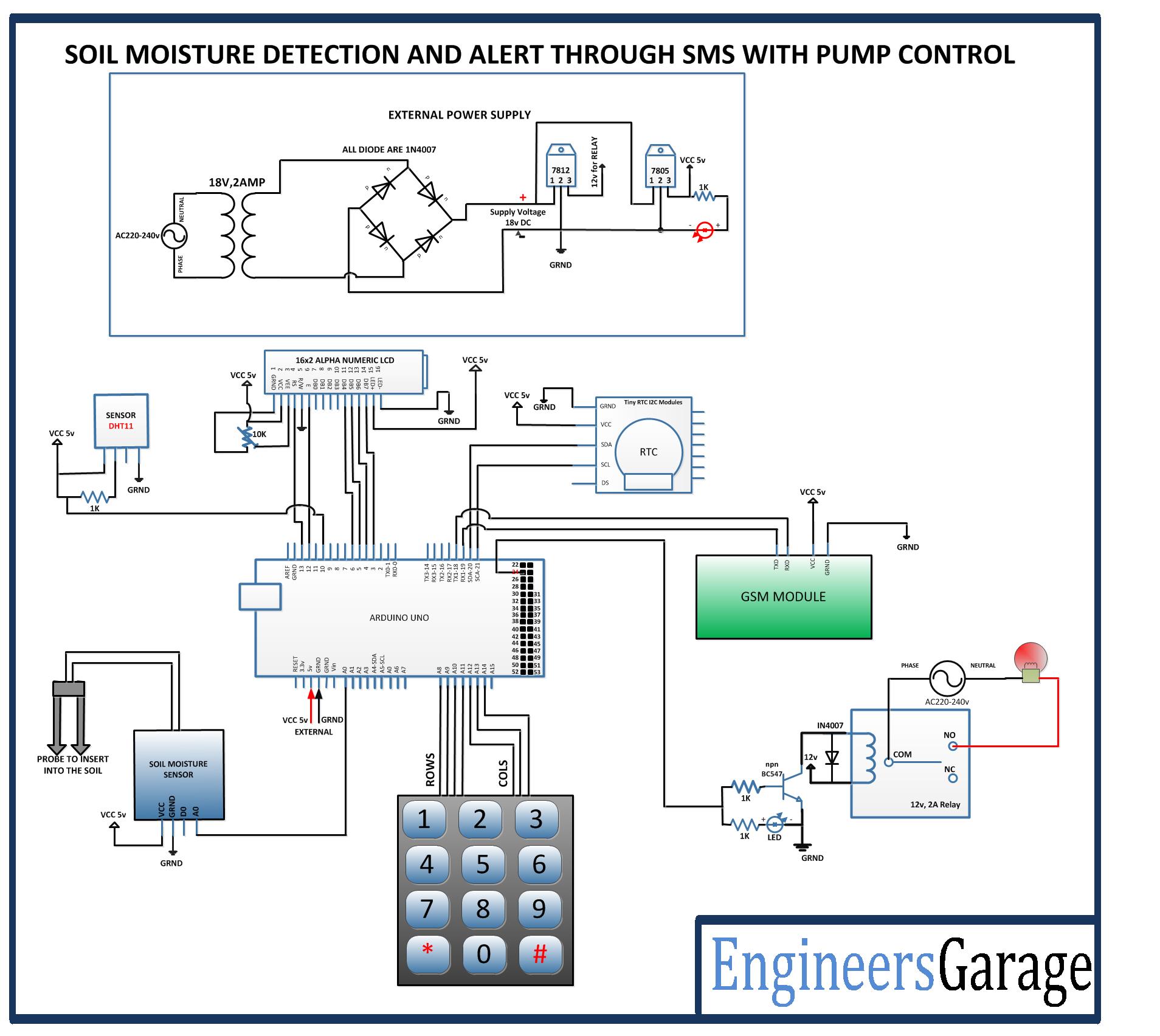 |
Project Video
Filed Under: Electronic Projects
Filed Under: Electronic Projects

Questions related to this article?
👉Ask and discuss on Electro-Tech-Online.com and EDAboard.com forums.
Tell Us What You Think!!
You must be logged in to post a comment.