In the previous tutorial, we learned about signal behavior and the role of a capacitor in a circuit. A capacitor stores electrical charge in the form of the electrostatic field in response to an applied voltage. It charges whenever the applied voltage increases (relative to the current-voltage across the capacitor) by allowing a charging current until the voltage across it equals and is opposite to the applied voltage. It discharges whenever the applied voltage decreases (relative to the current voltage across the capacitor) by allowing a discharging current through it in the opposite direction until the voltage across it equals and is opposite to the applied voltage. The capacitor retains voltage across it when there is no change in voltage across it or it is left open-circuited. The capacitor allows current through it only when the voltage across it is varying. For constant DC voltages, it becomes an open circuit allowing no current through it.
Factors determining the capacitance of a capacitor
Any capacitor is basically two conducting plates separated by a dielectric medium. The following equation gives the capacitance of a capacitor:
C = ε * A / d
Where,
C = Capacitance of the capacitor
ε = Absolute permittivity of the dielectric medium
A = surface area (in Metre2) of conducting plates parallel to each other
d = distance between the conducting plates
The capacitance of a capacitor is proportional to the absolute permittivity of the dielectric material used and the effective surface area of the conducting plates (the surface area of the conducting plate smallest between the two). At the same time, it is inversely proportional to the distance between the conducting plates. The absolute permittivity of a dielectric medium is related to the absolute permittivity of free space by the following equation:
ε = ε0 * εr
Where,
ε = Absolute permittivity of the dielectric material
ε0 = Absolute permittivity of free space or vacuum
εr = Relative permittivity of dielectric medium (to free space or vacuum)
Practical construction of a capacitor
Any capacitor is designed to achieve a nominal capacitance while keeping the size of the capacitor as small as possible. Therefore, manufacturers try to achieve maximum capacitance in construction. The capacitance of a capacitor can be maximized in the following three ways:
1) Using a suitable dielectric medium – The absolute permittivity of dry air is approximately equal to that of free space. If the absolute permittivity of free space is considered 1, that of dry air is 1.0006. By using a dielectric material having greater absolute permittivity, the capacitance of a capacitor can be increased many times. There are a variety of materials that are used as a dielectric medium in capacitors. Some of the commonly used dielectric materials are listed in the following table with their relative permittivity (dielectric constants):
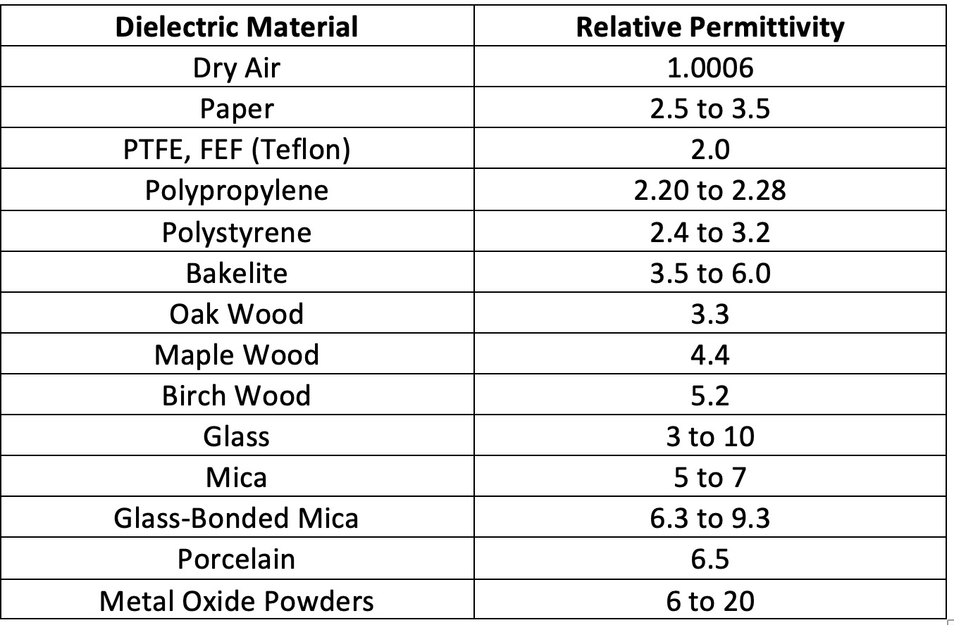
Using a suitable dielectric material, like mica, in place of dry air, the capacitance can be increased 5 to 7 times.
2) Increasing surface area – The more the surface of conducting plates are parallel to each other, the greater the capacitance. One way of increasing the surface area is multi-plate capacitors. In a multi-plate capacitor, the conducting surfaces are designed as multiple conducting sheets connected to a common lead. The two conducting sheet arrays are paired such that in one of the conductors, only one surface of the outer sheets remains in contact with the dielectric medium. In contrast, with the other conductor, both surfaces of the outer sheets stay in contact with the dielectric medium.
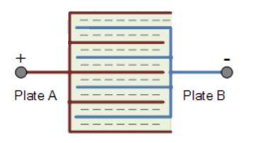
Image showing the construction of a multi-plate capacitor
A nine-plate capacitor is shown in the above image. One of the leads of the above capacitor has five plates, while the other lead has four plates connected. The above capacitor has eight times the greater surface area, so eight times greater capacitance. The following equation gives the capacitance of a multi-plate capacitor:
C = ε * (n-1) *A / d
Where n is the number of plates in the multi-plate capacitor, and A is the surface area of each plate.
3) Reducing the distance between plates – The capacitance can be increased by minimizing the distance between the plates. However, this aspect has practical limitations (like leakage current).
Types of capacitors
The capacitors are classified by the dielectric material used in their construction. There are a variety of dielectric materials used in the construction of capacitors. Some of the common types of capacitors are following –
1) Paper
2) Mica
3) Plastic Film
4) Glass
5) Ceramic
6) Electrolyte
7) Semiconductor
8) Variable
Polarized and non-polarized capacitors
While most capacitors can be connected in a circuit without considering the polarity of the applied voltage across them, electrolyte capacitors have a positive and a negative terminal. The positive electrode of the electrolyte capacitor should be connected only to the positive terminal of a battery (direction of the current entering the capacitor) and the negative electrode to the negative terminal of a battery (direction of the current leaving the capacitor). Due to their fixed polarity in any circuit, the electrolyte capacitors are called Polarized Capacitors. The other types of capacitors, not require a connection in a fixed polarity are called Non-Polarized Capacitors. Polarized capacitors can be used only in DC applications.
Key Performance Indicators of a capacitor
Like resistors or other electronic components, capacitors also exhibit several electrical properties and some non-ideal characteristics. These properties and characteristics can be an important consideration when selecting a circuit’s capacitor. The same can be taken as key performance indicators of a capacitor. The KPIs associated with the capacitors are following –
1) Nominal Capacitance – Nominal Capacitance of a capacitor is the capacitance supposed to be offered by a capacitor. This is the most important property of a capacitor and is marked on its body along with the working voltage. The actual capacitance provided by the capacitor may not be the same as the nominal capacitance, as the capacitance changes with the frequency of the applied signal and the ambient temperature. The nominal capacitance of standard capacitors is expressed in Microfarad (10-6F), Nanofarad (10-9F) and Picofarad (10-12F).
2) Working Voltage – The Working Voltage, or DC Working Voltage, is the maximum continuous voltage a capacitor can operate without breaking or damaging. This is generally the DC voltage rating marked on the body of a capacitor along with its nominal capacitance. The AC signals are generally specified RMS voltage levels. The peak voltage level of any AC signal is 1.414 times the RMS voltage. So, when using a capacitor in an AC circuit, its working voltage is comparable to the peak voltage of the AC signal and not the RMS voltage. Selecting a capacitor with a working voltage at least 1.5 times or twice the voltage specified for a given circuit is always safe. The most common working voltages for standard capacitors are 6.3V, 10V, 16V, 25V, 30V, 35V, 40V, 50V, 63V, 100V, 160V, 200V, 250V, 400V, 450V, 500V and 1000V.
3) Forming Voltage – Forming Voltage or Test Voltage is the maximum voltage the capacitor can withstand. It can be found in the datasheet of the capacitor supplied by its manufacturer. A capacitor should rarely be exposed to its test voltage.
4) Tolerance – Tolerance indicates the variation of the actual capacitance of a capacitor from its nominal capacitance. Typically, capacitors have a capacitance of 10% or 5%. Some capacitors can have a tolerance as low as 1%. The tolerance of the capacitors can even range between 20% and 80% depending upon the intended application. The tolerance of capacitors is expressed as a plus-minus value in Picofarad for low-value capacitors. In contrast, it is expressed as a percentage change in capacitance for high-value capacitors.
5) Leakage Current – Leakage current is a small amount of current that is leaked through the dielectric medium of the capacitor due to the strong electrostatic field on its plates. The leakage current is generally in nano amperes. It is related to the dielectric constant (relative permittivity) of the dielectric medium used in the capacitor. The lower the dielectric constant, the greater the leakage current.
The leakage current counts to the dissipation factor of a capacitor. Generally, leakage current is very low, often indicated as insulation or leakage resistance in datasheets. It is modeled as a parallel resistance leaking current through the pure capacitor. In electrolyte capacitors, the leakage current is quite significant and is usually indicated explicitly in their datasheets as “leakage current.”
The leakage current is an important indicator when a capacitor has to be used for coupling circuits or charge storage. A capacitor that has to be used for coupling or storage of charge must have minimum leakage current. The leakage current, how low it may be, is always enough to discharge the capacitor over time without any applied voltage fully.
6) Polarization – It is always important to take note of polarization in the case of electrolyte capacitors. The positive terminal of a polarized capacitor should always be connected to a positive connection and a negative terminal with a negative connection. The negative terminal of polarized capacitors is usually indicated by a black strip, band, or arrows on one side of the capacitor. Connecting an electrolyte capacitor in reverse polarity will generate a reverse voltage, resulting in a large breakdown current that can damage the capacitor permanently.
7) Reverse Voltage – Reverse voltage is an indicator associated with polarized capacitors. It is the maximum voltage (or sum of all peak DC and AC ripple voltages) in reverse polarity that the polarized capacitor can withstand. Any voltage in reverse polarity beyond the ‘Reverse Voltage’ of the polarized capacitor can permanently damage it.
8) Ripple Current – The Ripple Current is the maximum RMS value of AC current that the capacitor can withstand. It is often indicated for 120Hz frequency and 85°C temperature until otherwise specified. The ripple current through a capacitor increases with an increase in frequency and a decrease in ambient temperature.
9) Temperature Rating – The capacitors generally have a working temperature range between -55°C to 125°C. The operating temperature range depends specifically on the type of capacitor. Like, plastic capacitors have a low-temperature range from -30°C to 70°C, and electrolyte capacitors have an operating temperature range of -40°C/-55°C to 85°C. The temperature changes affect the actual capacitance of the capacitor, ripple current through it, and may stress the capacitor by imposing environmental challenges. Like, at temperatures as low as -10°C, the electrolyte jelly of electrolyte capacitors starts freezing. Similarly, other dielectric mediums also undergo stress due to changes in ambient temperature.
10) Temperature Coefficient – Like resistors, capacitors have either positive or negative temperature coefficients. The temperature coefficient of capacitors is expressed in Parts Per Million (PPM) per degree centigrade. The positive temperature coefficient is generally expressed by the letter P followed by a rating in PPM/°C, like P100 indicates a positive temperature coefficient equal to 100 PPM/°C. Similarly, the negative temperature coefficient is indicated by the letter ‘N’ followed by a rating in PPM/°C. The capacitors may have a zero temperature coefficient for a range of temperatures, which is indicated by a temperature coefficient expressed by the letters ‘NPO’.
In some circuits, where there should be minimum tolerance for capacitance, capacitors with negative and positive temperature coefficients can be connected in series or parallel to cancel out the effects of temperature on capacitance. The capacitors of positive and negative temperature coefficients can also be connected to cancel out the effect of temperature on other components of a circuit, like resistors and inductors. When connecting capacitors of positive and negative temperature coefficients to cancel out temperature effects, careful calculations must be done to find out effective capacitance over a range of temperatures.
11) Equivalent Series Resistance (ESR) – The Equivalent Series Resistance (ESR) of a capacitor is the internal resistance of the capacitor due to the DC resistance of the plates, the effective resistance of the dielectric medium, and resistance at the contact of dielectric and the conductor plates. This is the pure resistance offered by the capacitor, which causes energy loss by heating the capacitor during charging and discharging the capacitor by an AC signal. The ESR of a capacitor is modeled as a resistance connected in series to the pure capacitance. The ESR, like the capacitance, is frequency dependent and serves as a dynamic series resistance of the capacitor.
ESR is counted among the operating losses of the capacitor. It is an important indicator as it determines the loss of electrical energy in the case of coupling capacitors and maximum attenuation in the case of bypass and filter capacitors. The higher the ESR, the greater the RC constant (time required to charge or discharge) of the capacitor, as a capacitor with a higher ESR will offer more resistance to charging or discharging current.
12) Dielectric Absorption – The dielectric absorption refers to residual voltage left at the terminals of the capacitor after full discharging. Generally, this voltage is not significant but can be a serious concern in the case of sampling capacitors used in analog to digital converter circuits.
13) Self Inductance – Self-inductance is inductance induced in a capacitor at high frequencies. This inductance can influence the impedance of the capacitor at high frequencies and may determine which high-frequency currents the capacitor will be able to bypass. The ESR, dissipation factor, dielectric absorption, and self-inductance are counted among the operating losses of a capacitor.
The capacitors need to be handled carefully. The high-value capacitors (capacitance greater than 0.01 uF) used in high voltage circuits can have a residual or un-discharged voltage that can give a DC shock on contact. So, a high-value capacitor must be discharged by shorting its terminals using a screwdriver while troubleshooting such circuits. In the next article, we will discuss different types of capacitors and their technical specifications.
Filed Under: Featured Contributions

Questions related to this article?
👉Ask and discuss on EDAboard.com and Electro-Tech-Online.com forums.
Tell Us What You Think!!
You must be logged in to post a comment.