Engineers Garage

  • Projects and Tutorials
    • Circuit Design
    • Electronic Projects
      • 8051
      • Arduino
      • ARM
      • AVR
      • PIC
      • Raspberry pi
      • STM32
    • Tutorials
    • Components
  • Articles
    • Tech Articles
    • Insight
    • Invention Stories
    • How to
    • What Is
  • News
    • EE Design News
    • DIY Reviews
    • Guest Post
    • Sponsored Content
  • Forums
    • EDABoard.com
    • Electro-Tech-Online
    • EG Forum Archive
  • Digi-Key Store
    • Cables, Wires
    • Connectors, Interconnect
    • Discrete
    • Electromechanical
    • Embedded Computers
    • Enclosures, Hardware, Office
    • Integrated Circuits (ICs)
    • Isolators
    • LED/Optoelectronics
    • Passive
    • Power, Circuit Protection
    • Programmers
    • RF, Wireless
    • Semiconductors
    • Sensors, Transducers
    • Test Products
    • Tools
  • EE Resources
    • DesignFast
    • LEAP Awards
    • Oscilloscope Product Finder
    • Video
    • White Papers
    • Webinars
  • EE Learning Center
  • Women in Engineering

Multimeter Tutorial: How to test Continuity

April 6, 2013 By Vaibhav Jain

Continuity Test is a method to check current flow across any metallic path. Through this test, any unwanted circuit breaks or shorted connections can be put to verification. Continuity can be tested between any two circuit connections.

Apparatus: Multimeter, connecting probes, circuit board.

Step 1: Take the circuit board of which you want to test the continuity.

Step 2: Map the traced tracks and corresponding electronic components soldered on them.
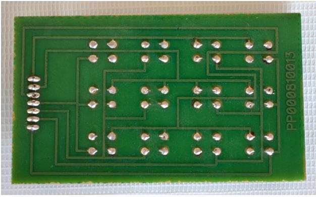
 

Image showing soldering of the PCB

Fig. 1: Image showing soldering of the PCB

Step 3: Turn the knob on the multimeter towards the continuity section

Step 4: Testing leads should be connected to the multimeter in the same manner as shown in the image below.
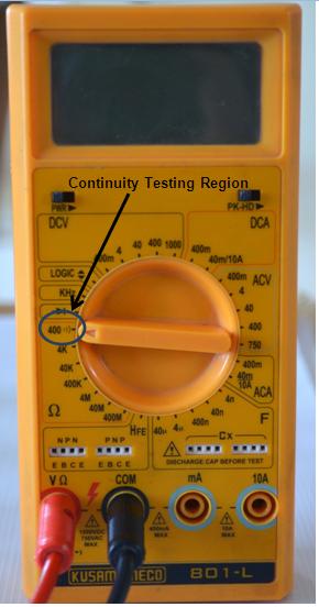
Image showing Multimeter set to Continuity Testing Region

Fig. 2: Image showing Multimeter set to Continuity Testing Region

Different multimeters have different location of continuity section. In this model it’s on 400 ohm.

Step 5:Select the metallic path of which you want to check the continuity and place one testing lead at the starting terminal and another at the other.
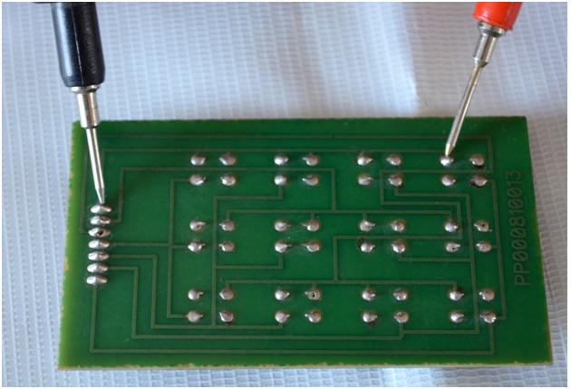
Image showing multimeter probes connected to PCB tracks for testing

Fig. 3: Image showing multimeter probes connected to PCB tracks for testing

Step 8: After placing the leads on their position the multimeter will produce a continuous beep sound indicating that track is continuous and there is no breakage in the track.

Related Articles Read More >

Introduction to LUFA
Introduction to Wireless Modules
ADC with NRF24LE1 (Part 2/14)
Interrupts with NRF24LE1 (Part 3/14)

HAVE A QUESTION?

Have a technical question about an article or other engineering questions? Check out our engineering forums EDABoard.com and Electro-Tech-Online.com where you can get those questions asked and answered by your peers!


Featured Tutorials

  • Introduction to Wireless Modules
  • ADC with NRF24LE1 (Part 2/14)
  • Interrupts with NRF24LE1 (Part 3/14)
  • Power Failure Indicator in NRF24LE1 (Part 4/14)
  • Using EEPROM of NRF24LE1 (Part 5/14)
  • PWM with NRF24LE1 (Part 6/14)

Stay Up To Date

Newsletter Signup

EE Training Center Classrooms

“ee

“ee

“ee

“ee

“ee

Recent Articles

  • Introduction to LUFA
  • What are the different types of integrated circuits?
  • Introduction to Wireless Modules
  • ADC with NRF24LE1 (Part 2/14)
  • Interrupts with NRF24LE1 (Part 3/14)

RSS EDABOARD.com Discussions

  • How to find 1's and 2's complement without using CMA operation in 8085 microprocessor?
  • Non-Inverting Amplifier (AC Coupled) : How to solve this circuit with lower and high frequency?
  • Electrolytic capacitor lifetime and rated voltage?
  • Syntax error in verilog
  • 2SC1971 Vs 2SC1972

RSS Electro-Tech-Online.com Discussions

  • Wirer up stereo needle
  • Learning C
  • Post some funny stuff...
  • Looking for an SOIC socket
  • QA pass
Engineers Garage
  • Analog IC TIps
  • Connector Tips
  • DesignFast
  • EDABoard Forums
  • EE World Online
  • Electro-Tech-Online Forums
  • Microcontroller Tips
  • Power Electronic Tips
  • Sensor Tips
  • Test and Measurement Tips
  • 5G Technology World
  • About Us
  • Contact Us
  • Advertise

Copyright © 2021 WTWH Media LLC. All Rights Reserved. The material on this site may not be reproduced, distributed, transmitted, cached or otherwise used, except with the prior written permission of WTWH Media
Privacy Policy | Advertising | About Us

Search Engineers Garage

  • Projects and Tutorials
    • Circuit Design
    • Electronic Projects
      • 8051
      • Arduino
      • ARM
      • AVR
      • PIC
      • Raspberry pi
      • STM32
    • Tutorials
    • Components
  • Articles
    • Tech Articles
    • Insight
    • Invention Stories
    • How to
    • What Is
  • News
    • EE Design News
    • DIY Reviews
    • Guest Post
    • Sponsored Content
  • Forums
    • EDABoard.com
    • Electro-Tech-Online
    • EG Forum Archive
  • Digi-Key Store
    • Cables, Wires
    • Connectors, Interconnect
    • Discrete
    • Electromechanical
    • Embedded Computers
    • Enclosures, Hardware, Office
    • Integrated Circuits (ICs)
    • Isolators
    • LED/Optoelectronics
    • Passive
    • Power, Circuit Protection
    • Programmers
    • RF, Wireless
    • Semiconductors
    • Sensors, Transducers
    • Test Products
    • Tools
  • EE Resources
    • DesignFast
    • LEAP Awards
    • Oscilloscope Product Finder
    • Video
    • White Papers
    • Webinars
  • EE Learning Center
  • Women in Engineering