This is the article to explain the implementation of mass storage in the USB module of the LPC1768. For setting up the Environment for the development of ARM cortex M3 is well discussed in this article.
The LPC 1768 is ARM Cortex- M3 based Microcontrollers for embedded application features in low power consumption and a high level of integration. The ARM Cortex M3 is designed in a such way to enhance debug features and a higher level of system integration. It clocks at a CPU frequency of 100 MHz, and incorporates a 3-stage pipeline and uses a Harvard architecture with separate local instruction and data buses for third bus peripherals. The ARM Cortex- M3 CPU have an internal pre-fetch unit to support speculative branching. The peripheral components include 512KB of flash memory, 64kb of data memory, Ethernet MAC, USB OTG, 4 UART’s, 8-channel general purpose DMA controller, 2 SSP Controllers, 10-bit DAC, Quadrature encoder interface, SPI interface, 3 I2C bus interface, 2 input plus 2 outputs I2S bus interface, 4 general purpose timers, ultra-low power Real-Time Clock (RTC) with separate battery supply, and up to 70 general purpose I/O pins, 6-output general purpose PWM. The LPC1768/66/65/64 is pin-compatible with the 100-pin LPC236x ARM7-based Microcontroller series.
This USB example project implements a Mass Storage Device (Memory Stick) that connects via the USB interface to the PC. A Mass Storage Device does not require any special USB driver, since the support is already built into Windows or Linux. Therefore Mass Storage Devices can be directly connected to the computer.
The USB mass storage device class (also known as USB MSC or UMS) is a set of computing communications protocols defined by the USB Implementers Forum that makes a USB device accessible to a host computing device and enables file transfers between the host and the USB device. To a host, the USB device acts as an external hard drive.
USB:
Universal serial Bus (USB), a connection technology for attaching peripheral devices to a computer, providing fast data exchange. USB connects more than computers and peripherals. USB gives you a single, standardized, easy-to-use way to connect up to 127 devices to a computer.
Interfacing USB:
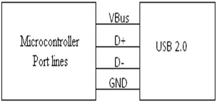
Below figure shows how to interface the USB to microcontroller. The USB is a 4 wire bus that supports communication between a host and a number (127 max.) of peripherals. In USB data cable Data+ and Data- signals are transmitted on a twisted pair. No termination needed. Half-duplex differential signaling helps to combat the effects of electromagnetic noise on longer lines. Contrary to popular belief, D+ and D- operate together; they are not separate simplex connections.

Fig. 1: Block Diagram Of Usb Interfacing Microcontroller
Interfacing USB with LPC2148:
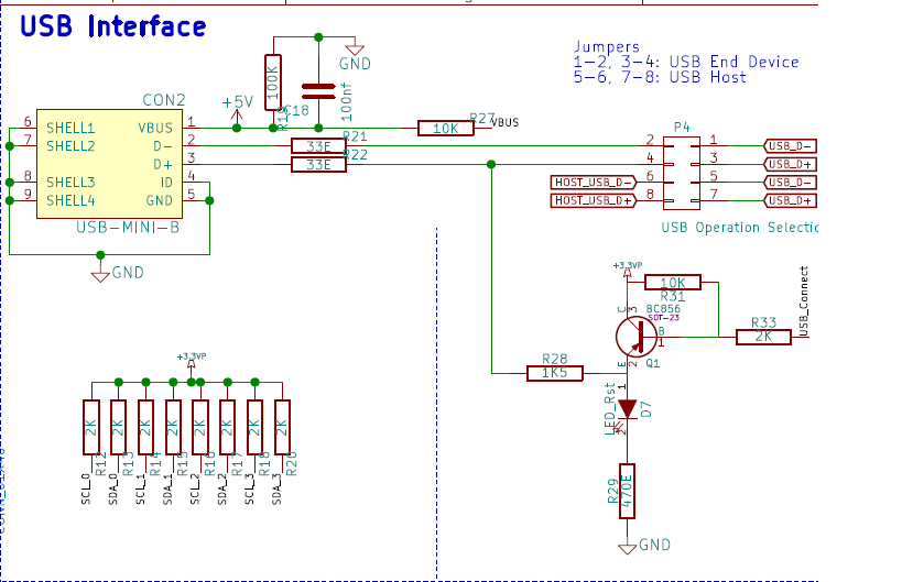
The LPC1768 controller enables 12 Mb/s data exchange with a USB host controller. It consists of register interface, serial interface engine, endpoint buffer memory and DMA controller. The input, output signals and a USB Bus are used to connect with controller. The LPC2148 controller read the USB voltage as power supply for controlling peripherals without having an external voltage. The LPC1768 USB takes supply voltage either from USB or external power supply by using a Jumper connection.
Circuit Diagram to Interface USB 2.0 with LPC1768:

Fig. 2: Circuit Diagram To Interface USB 2.0 With LPC1768
Create a project using Keil uvision4 for LPC1768 Microcontroller:
In this section, we will start creating a project in Keil MDK we have already installed Keil µVision and Co-MDK Plug-in + CoLinkEx Drivers required for the CoLinkEx programming adapter. You can start by downloading the project files and kick start your practical experiment.
To build this example, first download and extract the quick start code base.
After downloading, upload the program to the LPC1768 Board, follow these steps to run the program.
Installing the USBMEM Device:
-
Disconnect the USB power cable from the board.
-
Wait 10 seconds.
-
Re-connect the USB power cable to the board.
The Windows operating system displays a “Found New Hardware” message, but you don’t have to load any special drivers. Because support is built into Windows or Linux, a Mass Storage Device does not require a special USB driver.
-
Review the status of the USB Controllers using the Device Manager.
-
Right click on My Computer to open the System Properties – Hardware dialog.
-
Then click on Device Manager.
-
Right-click on the USB Mass Storage Device to open the Properties dialog which contains the description and status of the HID device.
Running the USBMEM Device:
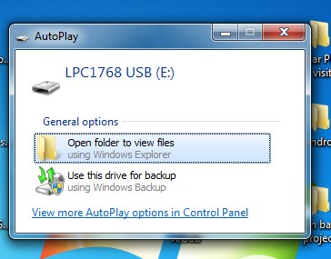
After the installation of the Mass Storage Device, Autoplay window will open and ask you to select one of the options. Open Windows File Explorer and move files to and from the Mass Storage Device.

Fig. 3: Running USBMEM Device In LPC1768
Note: Because the Mass Storage Device only has 16KB of RAM in the LPC2148 device, the storage capacity of this USB “drive” is limited..
Project Source Code
###The codes are linked in Description ###
Project Video
Filed Under: ARM.
Filed Under: ARM.


Questions related to this article?
👉Ask and discuss on Electro-Tech-Online.com and EDAboard.com forums.
Tell Us What You Think!!
You must be logged in to post a comment.