In this tutorial, we’ll learn how to detect fire or a flame using Arduino. Since fire generates heat, it’s possible to measure it via a sensor that tracks the temperature of the environment and converts it into data that can be monitored. However, a temperature sensor is not always a reliable solution for distinguishing fire from atmospheric heat.
Instead, studying the optical properties of fire can provide greater accuracy and detection capabilities. For example, fire emits infrared radiation (IR), which is stronger and easier to detect compared to the heat generated in other sources.
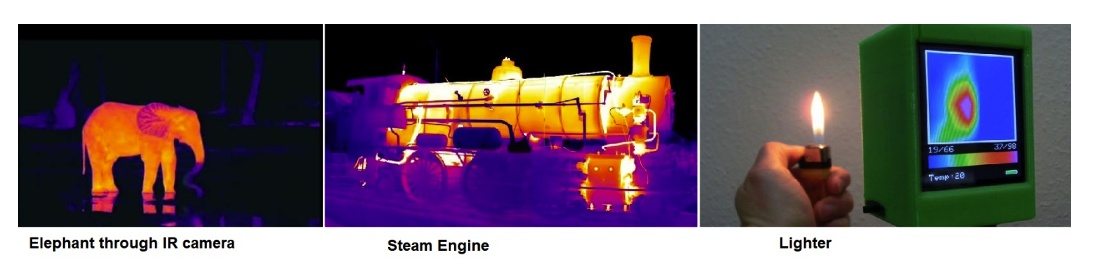
In the images below, the IR from different objects is visible. As you can see, the IR radiation from the lighter shows a dark red spot on the screen, which indicates fire. So clearly, IR detection is the ideal solution.
Most IR cameras for do-it-yourself (DIY) applications are expensive so choose wisely. There are now smaller IR sensors on the market, which are well-suited for this project. An IR detector is typically the most cost-effective and reliable choice.
The IR camera’s screen is made up of an array of LED, IR thermal sensors (or detectors) that create the image taken.
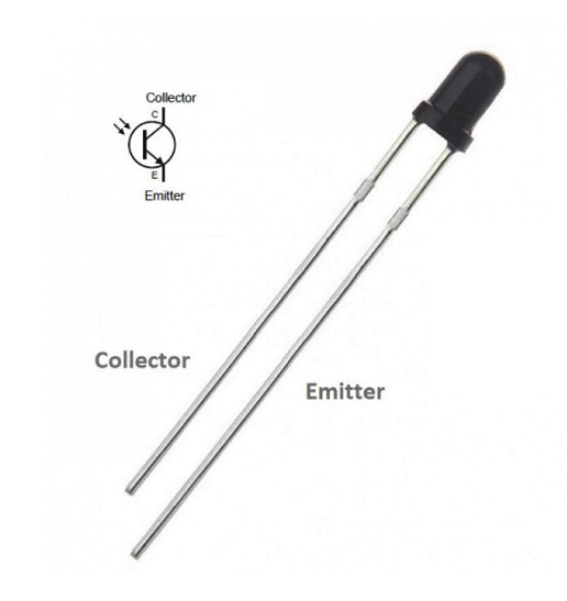
An infrared sensor LED
The electrical symbol of an IR sensor is similar to an NPN transistor except for the base. In an infrared sensor, the IR light source falls on the base, which is protected inside the plastic case.
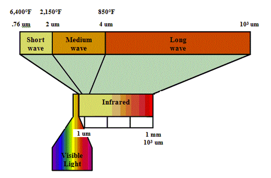
The IR waves are divided into sub-categories and most of the IR sensors measure one particular sub-category. For instance, the IR detector shown above can measure 940nm wavelengths so it falls into the “short waves detector” sub-category.
As an example, a TV remote also works on IR transmission and uses IR LEDs.
A simple DIY IR circuit is below. An operational amplifier is a must in this case to raise the IR detector’s output. The IR detector LEDs’ forward voltage is 1.6v.

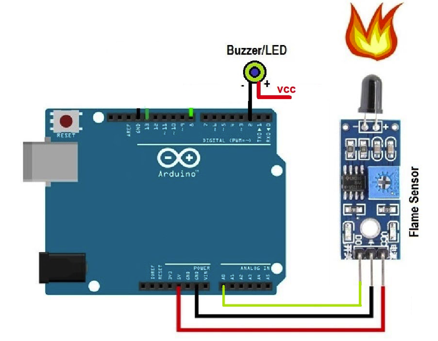
For this project, it’s possible to put together the above DIY IR circuit or use a pre-assembled IR module. The circuit diagram is below. We decided to use a pre-assembled IR module.
Circuit diagram
The Arduino IR detector module has two outputs: analog and digital. For the digital output, it’s necessary to set a threshold and, when the IR value goes above this threshold, the digital output pin is set to HIGH. Otherwise, it remains on LOW.
The threshold can be adjusted by rotating the variable resistor knob back and forth. The advantage of setting it is that you can ensure only activity that’s abnormal is detected and any typical surrounding IR is surpassed. The analog output detects the IR that’s usually present in the environment. In this mode, the sensor always outputs a value. Any spikes in output are recorded when the sensor is placed in front of a flame or fire.
We’re using the IR detector in analog mode. A buzzer is connected to Arduino’s pin#2. The buzzer’s alarm goes off anytime high spikes of IR are detected by the sensor.
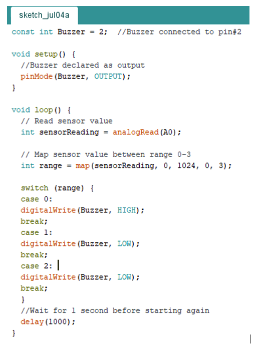
Project code
First, we defined the Arduino pin (2), which is connected to the buzzer. In the setup function, we declared the pin as the output.
The main loop is where the sensor value is read. We mapped the sensor value against a range of 0-3. The Arduino ADC max reading is 1024. We, then, divided 1024 in the range of 0-1, 1-2, and 2-3. The buzzer will buzz when the IR detector value falls between 0 and 1.
Where to purchase the parts?
Filed Under: Microcontroller Projects

Questions related to this article?
👉Ask and discuss on EDAboard.com and Electro-Tech-Online.com forums.
Tell Us What You Think!!
You must be logged in to post a comment.