Engineers Garage

  • Electronic Projects & Tutorials
    • Electronic Projects
      • Arduino Projects
      • AVR
      • Raspberry pi
      • ESP8266
      • BeagleBone
      • 8051 Microcontroller
      • ARM
      • PIC Microcontroller
      • STM32
    • Tutorials
      • Sensor Series
      • 3D Printing
      • AI
      • ARDUINO Compatible Coding
      • Audio Electronics
      • Battery Management
      • Beginners Electronics Series
      • Brainwave
      • Digital electronics (DE)
      • Electric Vehicles
      • EMI/EMC/RFI
      • EVs
      • Hardware Filters
      • IoT tutorials
      • LoRa/LoRaWAN
      • Power Tutorials
      • Protocol
      • Python
      • RPI Python Programming
      • Sensors
      • USB
      • Thermal management
      • Verilog
      • VHDL
    • Circuit Design
    • Project Videos
    • Components
  • Articles
    • Tech Articles
    • Insight
    • Invention Stories
    • How to
    • What Is
  • News
    • Electronic Product News
    • Business News
    • Company/Start-up News
    • DIY Reviews
    • Guest Post
  • Forums
    • EDABoard.com
    • Electro-Tech-Online
    • EG Forum Archive
  • DigiKey Store
    • Cables, Wires
    • Connectors, Interconnect
    • Discrete
    • Electromechanical
    • Embedded Computers
    • Enclosures, Hardware, Office
    • Integrated Circuits (ICs)
    • Isolators
    • LED/Optoelectronics
    • Passive
    • Power, Circuit Protection
    • Programmers
    • RF, Wireless
    • Semiconductors
    • Sensors, Transducers
    • Test Products
    • Tools
  • Learn
    • eBooks/Tech Tips
    • Design Guides
    • Learning Center
    • Tech Toolboxes
    • Webinars & Digital Events
  • Resources
    • Digital Issues
    • EE Training Days
    • LEAP Awards
    • Podcasts
    • Webinars / Digital Events
    • White Papers
    • Engineering Diversity & Inclusion
  • Guest Post Guidelines
  • Advertise
  • Subscribe

Virtual Retinal Display

By Shalem Pravas June 14, 2020

A machine consists of many sub-systems working together to perform a certain task. The information from the electronic devices is retrieved from the machine sub-systems as binary code. All this information is presented in a user-readable format through a display device. The display technology has seen rapid growth in the past few decades from the old CRT (Cathode Ray Tube) displays to the presently in demand LCD (Liquid Crystal Display) and LED (Light Emitting Diode) displays. The LCDs and LEDs consist of two dimensional arrays of individual display units (pixels) whose number to size of display determines the clarity of the display (resolution). These display units which we encounter on a daily basis (LCDs and LEDs) are pixel based display systems where these individual pixels form an image by combining individual colors. The colors are formed by different intensities of the primary colors RGB (Red, Green and Blue) or CMYK (Cyan, Magenta, Yellow and Black) combinations. But these technologies have a poor reputation when it comes to image quality, weight and power consumption when they need to be considered for application in wearable technology.

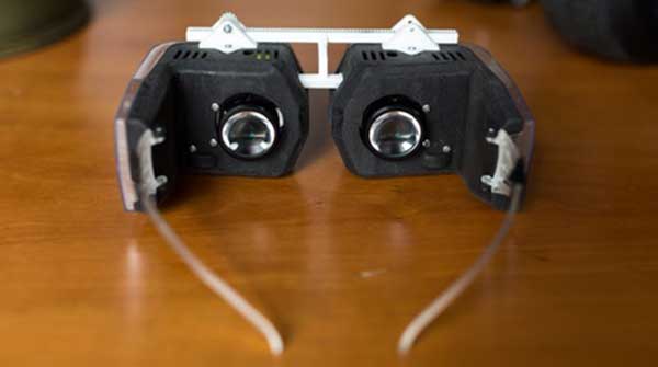
This is where the emerging concept of Virtual Retinal Display comes into picture. It diminishes the gap between the screen and the retina to a zero by directly throwing light on the retina which is just like how we view the world around us. It was developed at the Human Interface Technology Laboratory (HIT Lab) in the University of Washington by Dr. Thomas A. Furness III. The VRD technology can produce images by scanning low-power laser light directly onto the retina which will create high contrast, high resolution and bright images. This is especially designed to offer more interactive and immersive experience in Virtual Reality and Augmented Reality technologies. It provides a wide field of view with absolutely no background disturbance. In this article, we will discuss the aspects and features of the VRD and some products that have released recently in the market like the glyph by Avegant

1 OVERVIEW

The advent of virtual and augmented reality has seen a requirement for a display device which is more suitable for visual interaction. A wide field of view, which can be achieved in a pixel based display by either making a curved display or a curved lens, but this would just be increasing the cost which would just discourage this tech to take off commercially. The VRD would scale down (to a great extent) the size of the display while giving better quality images along with an immersive experience. It would alsooffer a more personal viewing experience which would be not just a luxury but a necessity in certain applications such as in surgical practices. So, what better way to view images than through the biological way in which eyes receive direct light from our surrounding environment

The VRD technology uses scanned light beams projected directly onto the retina. A small spot on the retina is focused on which the whole image is casted in the form of a raster image (array of color spaces but different from pixels). The production costs to develop the laser and optical systems will be inexpensive when mass produced. The VRD system consists of low cost light sources, optics and controllers.The combined assembly should be small enough to fit on a spectacle frame.
2 CONSTRUCTION
The basic system of the VRD consists of six parts;
1. Video Source
2. Control and Drive Electronics
3. Photon Source
4. Modulation devices
5. Horizontal and Vertical Beam Scanning
6. Delivery Optics
Figure 1Basic system breakup of the VRD

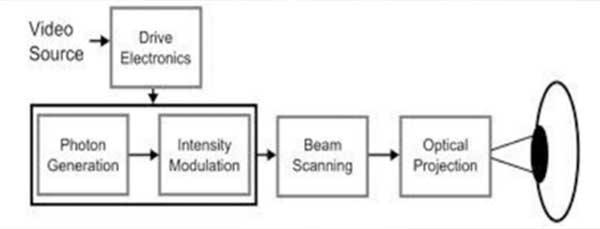
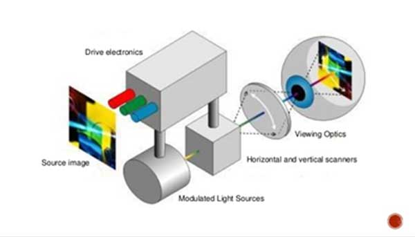
The video source gives the raw data about the image to the VRD system. The control and drive electronics control the modulators (acousto-optic) to store the image data and encode it into the pulse streams which gives information to the individual photon generators (Red, Green and Blue) to generate a mixed stream to recreate the image in pixel form. The photon (light) sources consist of individual monochrome lasers, a red laser diode (650nm wavelength), blue argon laser (488nm wavelength) and Helium-Neon green laser (488nm wavelength). The scanning consist of specially designed sets of Mechanical Resonance Scanners (MRS). The delivery optics consist of exit pupil lens which is aligned to the user’s eyes. In some cases, for achieving a transparent image for superimposition on the real world, beam splitters are used to modulate the intensities of the scanned light.

3 WORKING
The video signals are received by the VRD system from a graphics processing unit or a video camera. This information is used to modulate low power photon emitting sources like gas lasers, laser diodes or light emitting diodes in the colors of red, green and blue.
Figure 2Block diagram of the functioning of VRD

The combined light is passed through a single mode optical fiber. This strand carries the light to the main sub system of the VRD, the Mechanical Resonance Scanner (MRS). It consists of a polished mirror on a mount measuring 2cmx1cmx1cm. The mirror is oscillated by a magnetic field generated by coils which are present on the system mount. It oscillates at a frequency of 15 KHz and an angular range of 12 degrees. The movement of the mirror on the MRS produces a scanned light in the horizontal direction. This scanned light is passed through a mirror galvanometer which is a second set of MRS arranged in a different configuration to allow the vertical light scanning. The combination of vertical and horizontal light scan produces a two dimensional raster which is cast onto the focused spot on the retina.The scanned image can be sent through a mirror/combiner to superimpose the image onto to the real world view for the case of augmented reality.

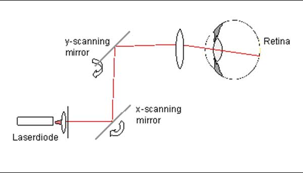
Figure 3Horizontal (X-Axis) and Vertical (Y-Axis) sweeping of the images through MRS

Another important strength is that the scanned light from the VRD is directly collected by the brain in the form of electric signal generated by the photoreceptors and tries to make sense of the image. Here, the human brain is providing computing power to the VRD and therefore reduces flickering as seen on CRT screens. Each unit of scanned image is projected on the retina for a short time (about 40 nanoseconds). Furthermore, it produces bright images sufficient for outdoor viewing along with a wide field of view while consuming energy in the scale of Nano watts.

4 COMPARISON TO SCREEN DISPLAYS

If there is a general pixel formation on the retina, then you might wonder how it is different from the conventional screen displays. The mode of illumination of illumination of the retina is different in VRD in a way that the scanned image is rapidly swept over the “Retinel” (analogous to the pixel in VRD) which means that it is not a stationary point on the retina but is more of a transient mode of projection which makes it a non-uniformly illuminated in time giving it a greater depth in detail and lower time of illumination during the refresh cycle. The light from the VRD is coherent (colors in phase with each other) and narrow band in wavelength producing crisp and accurate color reproduction. Unlike pixels, retinels can overlap with each other to for a smoother image and reduce separation of image and higher resolution.
5 VERDICT
On paper it might look like a harmful device considering it shoots lasers onto your eyes. But, it is quite safe due to the low intensities of the lasers. Its power output levels are lower to several orders than what is prescribed as the safe limit by American National Standard.
Figure 4The Avegant Glyph consumer model
One of the popular VRD enabled devices released during the Consumer Electronics Show 2016 in Las Vegas, is the Glyph by Avegant. It looks like a regular headphone set which fits on horizontally consisting of the VRD unit on the band along with high quality audio outputs. This actually uses LEDs as the photon source rather than the lasers. It consists of 2 million micro mirrors array to reflect the light onto the retina. The image is focused and scanned onto the retina at a high resolution of 1280x720p per eye along with a 400 field of view. It also has a head tracking feature to provide for VR (Virtual Reality) applications. 
High brightness, High contrast, high resolution, low power consumption and high brightness makes VRD an ideal candidate in various applications such as medical surgical displays, military, aerospace, head mounted displays as well as help improve the sight for patients with visual disabilities. VRD is a novel idea and is ready for getting absorbed into the latest tech around the world. It quite literally gives a fresh new look of the world.

Filed Under: Applications, AR/VR, Tech Articles


Next Article

← Previous Article
Next Article →

Questions related to this article?
👉Ask and discuss on Electro-Tech-Online.com and EDAboard.com forums.


Tell Us What You Think!! Cancel reply

You must be logged in to post a comment.

Submit a Guest Post

submit a guest post

EE TECH TOOLBOX

“ee
Tech Toolbox: Power Efficiency
Discover proven strategies for power conversion, wide bandgap devices, and motor control — balancing performance, cost, and sustainability across industrial, automotive, and IoT systems.

EE Learning Center

EE Learning Center
“engineers
EXPAND YOUR KNOWLEDGE AND STAY CONNECTED
Get the latest info on technologies, tools and strategies for EE professionals.

HAVE A QUESTION?

Have a technical question about an article or other engineering questions? Check out our engineering forums EDABoard.com and Electro-Tech-Online.com where you can get those questions asked and answered by your peers!


RSS EDABOARD.com Discussions.

  • CST Studio Suite 2021 – New Project Window Shows Black Screen
  • Introduction to the Principle of Human Detection by Millimeter-Wave Radar Modules
  • Biasing an AC signal
  • SiC FET turn-off in 2000W PFC
  • Why SG3525 + TL431 + PC817 feedback is not working on ±35 V push-pull SMPS?

RSS Electro-Tech-Online.com Discussions

  • restarting this Christmas project
  • desoldering
  • Unknown, to me, electric motor fitting
  • Can a small solar panel safely trickle-charge old NiMH AA batteries?
  • KiCad custom symbol definition correct approach

Featured Tutorials

Real Time Hardware Filter Design

  • Practical implementation of bandpass and band reject filters
    Practical implementation of bandpass and band reject filters
  • Practical application of hardware filters with real-life examples
    Practical application of hardware filters with real-life examples
  • A filter design example
    A filter design example
  • Types of filter responses
    Types of filter responses
  • What are the two types of hardware filters?
    What are the two types of hardware filters?
  • What are hardware filters and their types?
    What are hardware filters and their types?
More Tutorials >

Recent Articles

  • Taiwan Semiconductor adds 24-V automotive TVS devices
  • ST e-fuse controller enables fast, flexible automotive power protection
  • Posifa sensors improve low-flow accuracy in compact systems
  • Acopian releases low-profile power supplies rated to 900 W
  • Octavo Systems OSDZU-3 REF Development Platform

EE ENGINEERING TRAINING DAYS

engineering
Engineers Garage
  • Analog IC TIps
  • Connector Tips
  • Battery Power Tips
  • EDABoard Forums
  • EE World Online
  • Electro-Tech-Online Forums
  • EV Engineering
  • Microcontroller Tips
  • Power Electronic Tips
  • Sensor Tips
  • Test and Measurement Tips
  • 5G Technology World
  • Subscribe to our newsletter
  • About Us
  • Contact Us
  • Advertise

Copyright © 2025 WTWH Media LLC. All Rights Reserved. The material on this site may not be reproduced, distributed, transmitted, cached or otherwise used, except with the prior written permission of WTWH Media
Privacy Policy

Search Engineers Garage

  • Electronic Projects & Tutorials
    • Electronic Projects
      • Arduino Projects
      • AVR
      • Raspberry pi
      • ESP8266
      • BeagleBone
      • 8051 Microcontroller
      • ARM
      • PIC Microcontroller
      • STM32
    • Tutorials
      • Sensor Series
      • 3D Printing
      • AI
      • ARDUINO Compatible Coding
      • Audio Electronics
      • Battery Management
      • Beginners Electronics Series
      • Brainwave
      • Digital electronics (DE)
      • Electric Vehicles
      • EMI/EMC/RFI
      • EVs
      • Hardware Filters
      • IoT tutorials
      • LoRa/LoRaWAN
      • Power Tutorials
      • Protocol
      • Python
      • RPI Python Programming
      • Sensors
      • USB
      • Thermal management
      • Verilog
      • VHDL
    • Circuit Design
    • Project Videos
    • Components
  • Articles
    • Tech Articles
    • Insight
    • Invention Stories
    • How to
    • What Is
  • News
    • Electronic Product News
    • Business News
    • Company/Start-up News
    • DIY Reviews
    • Guest Post
  • Forums
    • EDABoard.com
    • Electro-Tech-Online
    • EG Forum Archive
  • DigiKey Store
    • Cables, Wires
    • Connectors, Interconnect
    • Discrete
    • Electromechanical
    • Embedded Computers
    • Enclosures, Hardware, Office
    • Integrated Circuits (ICs)
    • Isolators
    • LED/Optoelectronics
    • Passive
    • Power, Circuit Protection
    • Programmers
    • RF, Wireless
    • Semiconductors
    • Sensors, Transducers
    • Test Products
    • Tools
  • Learn
    • eBooks/Tech Tips
    • Design Guides
    • Learning Center
    • Tech Toolboxes
    • Webinars & Digital Events
  • Resources
    • Digital Issues
    • EE Training Days
    • LEAP Awards
    • Podcasts
    • Webinars / Digital Events
    • White Papers
    • Engineering Diversity & Inclusion
  • Guest Post Guidelines
  • Advertise
  • Subscribe