The mouse and the Keyboard form the standard input unit for a Personal computer. The QWERT keyboard which is used in the PC comes with a PS2 connector or USB port connector. The PS2 keyboard uses a simple synchronous serial protocol using only two wires for communication. Due to its simplicity the PS2 keyboards are widely used with simple microcontroller based boards also. The PS2 keyboard always acts as a slave device which can send the equivalent ASCII value of the key which has been pressed to its master device which can be a PC or a microcontroller.
Any AVR microcontroller based board which follows the standard Arduino schematic and is flashed with the Arduino bootloader can be called an arduino board. The arduino boot-loaderenables different Arduino boards to be connected and programmed with the Arduino IDE. The Arduino board used in this project is the Arduino pro-mini board and the IDE version of the arduino is 1.0.3 for windows.
The image of the Arduino pro-mini board and the Arduino IDE are shown below:

Fig. 2: Typical Arduino Pro-Mini Board

Fig. 3: Arduino IDE Software Window
Since the Arduino pro-mini board has no circuitary for interfacing it with the serial port or the USB port of the PC, an external USB to TTL converter board is required to connect it with the PC. This hardware helps in programming the Arduino board and also helps in the serial communication with the USB port of the PC.

Fig. 4: External USB to TTL converter board for programming Arduino and serial communication
It is assumed that the reader has gone through the project how to get started with the Arduino and tried out all the things discussed there. The image of the Xbee S1 series module used in this project is shown in the following image. Since the pitch of the pins of the modules are not breadboard compatible one can use the Xbee based design boards which comes with breadboard compatible pins.

Fig. 5: Xbee S1 Series Module
Since the Xbee modules communicate using serial communication protocol with the interfacing devices they can be connected to a microcontroller using a minimum of four pins, Power supply, and Ground, UART Data Out, and UART Data In pins. The Xbee modules have several digital and analog I/O pins apart from these pins and the pin out of an Xbee module is shown in the following table:
|
PIN |
DESCRIPTION |
|
1 |
Power Supply |
|
2 |
UART Data Out |
|
3 |
UART Data In |
|
4 |
Digital Output 8 (not supported as of 2/28/09) |
|
5 |
Module Reset (reset pulse must be at least 200 ns) |
|
6 |
PWM Output 0 / RX Signal Strength Indicator |
|
7 |
PWM Output 1 |
|
8 |
Do not connect |
|
9 |
DTR / Pin Sleep Control Line or Digital Input 8 |
|
10 |
Ground |
|
11 |
Analog Input 4 or Digital I/O 4 |
|
12 |
Clear-to-Send Flow Control or Digital I/O 7 |
|
13 |
Module Status Indicator |
|
14 |
Voltage Reference for A/D Inputs |
|
15 |
Associated Indicator, Analog Input 5 or Digital I/O 5 |
|
16 |
Request-to-Send Flow Control, Analog Input 6 or Digital I/O 6 |
|
17 |
Analog Input 3 or Digital I/O 3 |
|
18 |
Analog Input 2 or Digital I/O 2 |
|
19 |
Analog Input 1 or Digital I/O 1 |
|
20 |
Analog Input 0 or Digital I/O 0 |
Fig. 6: Pin Out of Xbee module
Since the Xbee modules communicate using serial communication protocol with the interfacing devices they can be connected to a microcontroller using a minimum of four pins, Power supply, and Ground, UART Data Out, and UART Data In pins.The pin number 2, UART Data Out is connected to the RX1 pin of the Arduino pro mini board and pin number 3 UART Data In is connected to the TX0 pin.
The keyboard always has 6 pin mini-DIN male connector for PS2 interface and the host device always has the corresponding female pin. The images and the pin-outs of the PS2 male and female connectors are shown in the following image, the only difference between the PS2 keyboard and mouse connectors are in their color.
The image of the PS2 male pin

Fig. 7: 6 Pin Mini-DIN Male Connector For PS2 Interface
The image of the PS2 female pin

Fig. 8: 6 Pin Mini DIN Female Connector Plug for PS2 interface
The pin-out of the PS2 male and female connectors

Fig. 9: Pin-Out Of PS2 Male Connector and Pin-Out Of PS2Female Connectors
When it comes to connecting the female connector with the circuit board one should be able to identify the pins at the bottom of the PS2 connector and the following image will be helpful.

Fig. 10: Bottom of Mini DIN Female Connector Plug for PS2 interface
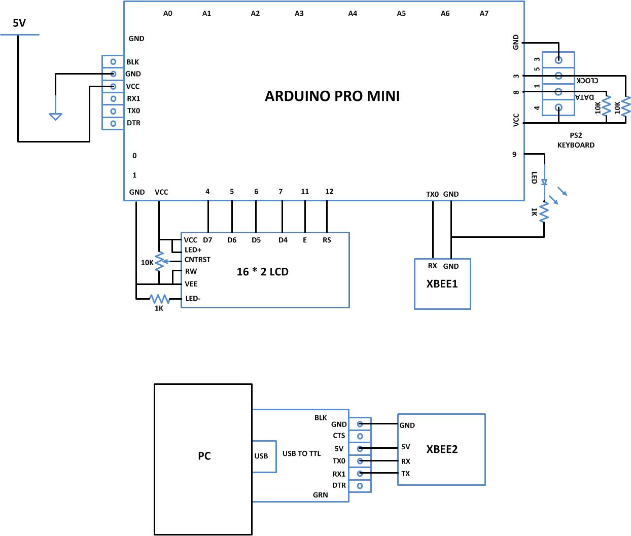
The implementation of the project which can receive the data from the PS2 keyboard and transmit the characters one typed on the keyboard to a remote computer through Xbee is represented using the following block diagram:

Fig. 11: Block Diagram Of Data Transmission bewteen Keyboard and Computer Using Xbee
The code written for this project reads the data from the PS2 keyboard using the custom PS2 library file called “PS2Keyboard.h” which has all the necessary routines for accessing a PS2 keyboard. The details of how to use this library to interface a PS2 keyboard is already discussed in a previous project on how to interface the PS2 keyboard with the Arduino. There are basically three functions which the user can directly make use in their code and are namely “keyboard.begin()”,keyboard.available() and “keyboard.read()”. The details of the functions are discussed in the following.
keyboard.begin()
The function keyboard.begin() is used to perform all the necessary things to initialize an ASCII keyboard using PS2 protocol. Once the initialization is done properly each time a key is pressed the keyboard starts sending the equivalent ASCII value of the key which has been pressed. The function takes one parameter and it is the number of the pin in the Arduino board which acts as the Data pin of the keyboard.
keyboard.available()
This function can be used to check if a data regarding a key press is available from the keyboard. This function is always called before calling the keyboard.read() function which is used to read the data from the keyboard. The function returns a non-zero positive value whenever a key press is detected.
keyboard.read()
The function keyboard.read() can be used to read the ASCII value of a key which has been pressed from the keyboard. The function does not take any parameter and it returns the ASCII value of the key. The function keyboard.read() is always called after the function keyboard.read() returns a non-zero positive value.
The Arduino board writes the PS2 keyboard data to the Xbee for transmission with the help of serial communication functions provided by the Arduino library. The functions like Serial.begin() which helps to initialize the serial port with a given baud rate, Serial.write() to send a data to the serial port, Serial.available() and Serial.read() functions to read data from the serial port are used in this project and they are already discussed in previous projects on how to do serial communication with the Arduino, how to send and receive serial data using arduino and how to do serial debugging with the Arduino. The method of interfacing a Xbee module and transmission of data using it is discussed in as previous project on how to interface Xbee module with Arduino.
When the coding is finished one can verify and upload the code to the Arduino board as explained in the project how to get started with the Arduino. As soon as the board is powered up the Xbee in the Arduino board automatically establishes communication with another Xbee which is connected to the serial port of a PC. The second Xbee board can be connected to the PC using the same USB to TTL converter board which has been used to program the Arduino board. The letters typed on the PS2 keyboard will get transmitted and can be read on the PC using any serial monitoring software or using the Arduino IDE’s serial monitoring software itself as explained in the project how to do serial debugging with the Arduino.
You may also like:


Project Source Code
### /*============================ EG LABS ===================================// Demonstration on how to wirelessly send ps2keyboard data using Xbee The circuit: LCD: * LCD RS pin to digital pin 12 * LCD Enable pin to digital pin 11 * LCD D4 pin to digital pin 7 * LCD D5 pin to digital pin 6 * LCD D6 pin to digital pin 5 * LCD D7 pin to digital pin 4 * LCD R/W pin to ground * 10K resistor: * ends to +5V and ground * wiper to LCD pin 3 * LED anode attached to digital output 9 * LED cathode attached to ground through a 1K resistor KEYBOARD: DATA PIN TO PIN NUMBER 8 CLOCK PIN TO PIN NUMBER 3 XBEE: RX PIN OF XBEE TO TX0 PIN OF ARDUINO SHORT THE GROUND PINS OF ARDUINO AND XBEE ============================== EG LABS ===================================*/ #include "PS2Keyboard.h" // include the library code: #include// initialize the library with the numbers of the interface pins LiquidCrystal lcd(12, 11, 7, 6, 5, 4); #define DATA_PIN 8 PS2Keyboard keyboard; void setup() { pinMode(9, OUTPUT); lcd.begin(16, 2); lcd.print("ENGINEERS GARAGE"); lcd.setCursor(0, 1); lcd.print("KEYBOARD to XBEE"); keyboard.begin(DATA_PIN); // initialize the PS2 keyboard Serial.begin(9600); Serial.println("ENGINEERS GARAGE"); delay(1000); digitalWrite(9, HIGH); } void loop() { if(keyboard.available()) // check if there is any data coming from the keyboard { char dat = keyboard.read(); // read the data from the keyboard Serial.write(dat); }else; } ###
Project Source Code
### Header File #include#include #include #include "Arduino.h" #include "PS2Keyboard.h" #include "binary.h" typedef uint8_t boolean; typedef uint8_t byte; int ps2Keyboard_DataPin; byte ps2Keyboard_CurrentBuffer; volatile byte ps2Keyboard_CharBuffer; volatile byte ps2Keyboard_BufferPos; // variables used to remember information about key presses volatile bool ps2Keyboard_shift; // indicates shift key is pressed volatile bool ps2Keyboard_ctrl; // indicates the ctrl key is pressed volatile bool ps2Keyboard_alt; // indicates the alt key is pressed volatile bool ps2Keyboard_extend; // remembers a keyboard extended char received volatile bool ps2Keyboard_release; // distinguishes key presses from releases volatile bool ps2Keyboard_caps_lock; // remembers shift lock has been pressed // vairables used in sending command bytes to the keyboard, eg caps_lock light volatile boolean cmd_in_progress; volatile int cmd_count; byte cmd_value; volatile byte cmd_ack_value; byte cmd_parity; volatile boolean cmd_ack_byte_ok; // sending command bytes to the keybaord needs proper parity (otherwise the keyboard // just asks you to repeat the byte) byte odd_parity(byte val) { int i, count = 1; // start with 0 for even parity for (i=0; i<8; i++) { if (val&1) count++; val = val>>1; } return count & 1; // bottom bit of count is parity bit } void kbd_send_command(byte val) { // stop interrupt routine from receiving characters so that we can use it // to send a byte cmd_in_progress = true; cmd_count = 0; // set up the byte to shift out and initialise the ack bit cmd_value = val; cmd_ack_value = 1; // the kbd will clear this bit on receiving the byte cmd_parity = odd_parity(val); // set the data pin as an output, ready for driving digitalWrite(ps2Keyboard_DataPin, HIGH); pinMode(ps2Keyboard_DataPin, OUTPUT); // drive clock pin low - this is going to generate the first // interrupt of the shifting out process pinMode(PS2_INT_PIN, OUTPUT); digitalWrite(PS2_INT_PIN, LOW); // wait at least one clock cycle (in case the kbd is mid transmission) delayMicroseconds(60); // set up the 0 start bit digitalWrite(ps2Keyboard_DataPin, LOW); // let go of clock - the kbd takes over driving the clock from here digitalWrite(PS2_INT_PIN, HIGH); pinMode(PS2_INT_PIN, INPUT); // wait for interrupt routine to shift out byte, parity and receive ack bit while (cmd_ack_value!=0) ; // switch back to the interrupt routine receiving characters from the kbd cmd_in_progress = false; } void PS2Keyboard::reset() { kbd_send_command(0xFF); // send the kbd reset code to the kbd: 3 lights // should flash briefly on the kbd // reset all the global variables ps2Keyboard_CurrentBuffer = 0; ps2Keyboard_CharBuffer = 0; ps2Keyboard_BufferPos = 0; ps2Keyboard_shift = false; ps2Keyboard_ctrl = false; ps2Keyboard_alt = false; ps2Keyboard_extend = false; ps2Keyboard_release = false; ps2Keyboard_caps_lock = false; cmd_in_progress = false; cmd_count = 0; cmd_value = 0; cmd_ack_value = 1; } // val : bit_2=caps_lock, bit_1=num_lock, bit_0=scroll_lock void kbd_set_lights(byte val) { // When setting the lights with the 0xED command the keyboard responds // with an "ack byte", 0xFA. This is NOT the same as the "ack bit" that // follows the succesful shifting of each command byte. cmd_ack_byte_ok = false; // initialise the ack byte flag kbd_send_command(0xED); // send the command byte while (!cmd_ack_byte_ok) ; // ack byte from keyboard sets this flag kbd_send_command(val); // now send the data } // The ISR for the external interrupt // This may look like a lot of code for an Interrupt routine, but the switch // statements are fast and the path through the routine is only ever a few // simple lines of code. void ps2interrupt (void) { int value = digitalRead(ps2Keyboard_DataPin); // This is the code to send a byte to the keyboard. Actually its 12 bits: // a start bit, 8 data bits, 1 parity, 1 stop bit, 1 ack bit (from the kbd) if (cmd_in_progress) { cmd_count++; // cmd_count keeps track of the shifting switch (cmd_count) { case 1: // start bit digitalWrite(ps2Keyboard_DataPin,LOW); break; case 2: case 3: case 4: case 5: case 6: case 7: case 8: case 9: // data bits to shift digitalWrite(ps2Keyboard_DataPin,cmd_value&1); cmd_value = cmd_value>>1; break; case 10: // parity bit digitalWrite(ps2Keyboard_DataPin,cmd_parity); break; case 11: // stop bit // release the data pin, so stop bit actually relies on pull-up // but this ensures the data pin is ready to be driven by the kbd for // for the next bit. digitalWrite(ps2Keyboard_DataPin, HIGH); pinMode(ps2Keyboard_DataPin, INPUT); break; case 12: // ack bit - driven by the kbd, so we read its value cmd_ack_value = digitalRead(ps2Keyboard_DataPin); cmd_in_progress = false; // done shifting out } return; // don't fall through to the receive section of the ISR } // receive section of the ISR // shift the bits in if(ps2Keyboard_BufferPos > 0 && ps2Keyboard_BufferPos < 11) { ps2Keyboard_CurrentBuffer |= (value << (ps2Keyboard_BufferPos - 1)); } ps2Keyboard_BufferPos++; // keep track of shift-in position if(ps2Keyboard_BufferPos == 11) { // a complete character received switch (ps2Keyboard_CurrentBuffer) { case 0xF0: { // key release char ps2Keyboard_release = true; ps2Keyboard_extend = false; break; } case 0xFA: { // command acknowlegde byte cmd_ack_byte_ok = true; break; } case 0xE0: { // extended char set ps2Keyboard_extend = true; break; } case 0x12: // left shift case 0x59: { // right shift ps2Keyboard_shift = ps2Keyboard_release? false : true; ps2Keyboard_release = false; break; } case 0x11: { // alt key (right alt is extended 0x11) ps2Keyboard_alt = ps2Keyboard_release? false : true; ps2Keyboard_release = false; break; } case 0x14: { // ctrl key (right ctrl is extended 0x14) ps2Keyboard_ctrl = ps2Keyboard_release? false : true; ps2Keyboard_release = false; break; } case 0x58: { // caps lock key if (!ps2Keyboard_release) { ps2Keyboard_caps_lock = ps2Keyboard_caps_lock? false : true; // allow caps lock code through to enable light on and off ps2Keyboard_CharBuffer = ps2Keyboard_CurrentBuffer; } else { ps2Keyboard_release = false; } break; } default: { // a real key if (ps2Keyboard_release) { // although ignore if its just released ps2Keyboard_release = false; } else { // real keys go into CharBuffer ps2Keyboard_CharBuffer = ps2Keyboard_CurrentBuffer; } } } ps2Keyboard_CurrentBuffer = 0; ps2Keyboard_BufferPos = 0; } } PS2Keyboard::PS2Keyboard() { // nothing to do here } void PS2Keyboard::begin(int dataPin) { // Prepare the global variables ps2Keyboard_DataPin = dataPin; ps2Keyboard_CurrentBuffer = 0; ps2Keyboard_CharBuffer = 0; ps2Keyboard_BufferPos = 0; ps2Keyboard_shift = false; ps2Keyboard_ctrl = false; ps2Keyboard_alt = false; ps2Keyboard_extend = false; ps2Keyboard_release = false; ps2Keyboard_caps_lock = false; cmd_in_progress = false; cmd_count = 0; cmd_value = 0; cmd_ack_value = 1; // initialize the pins pinMode(PS2_INT_PIN, INPUT); digitalWrite(PS2_INT_PIN, HIGH); pinMode(dataPin, INPUT); digitalWrite(dataPin, HIGH); attachInterrupt(1, ps2interrupt, FALLING); #if 0 // Global Enable INT1 interrupt EIMSK |= ( 1 << INT1); // Falling edge triggers interrupt EICRA |= (0 << ISC10) | (1 << ISC11); #endif } bool PS2Keyboard::available() { return ps2Keyboard_CharBuffer != 0; } // This routine allows a calling program to see if other other keys are held // down when a character is received: ie , , or // Note that this routine must be called after available() has returned true, // but BEFORE read(). The read() routine clears the buffer and allows another // character to be received so these bits can change anytime after the read(). byte PS2Keyboard::read_extra() { return (ps2Keyboard_caps_lock<<3) | (ps2Keyboard_shift<<2) | (ps2Keyboard_alt<<1) | ps2Keyboard_ctrl; } byte PS2Keyboard::read() { byte result; // read the raw data from the keyboard result = ps2Keyboard_CharBuffer; // Use a switch for the code to character conversion. // This is fast and actually only uses 4 bytes per simple line switch (result) { case 0x1C: result = 'a'; break; case 0x32: result = 'b'; break; case 0x21: result = 'c'; break; case 0x23: result = 'd'; break; case 0x24: result = 'e'; break; case 0x2B: result = 'f'; break; case 0x34: result = 'g'; break; case 0x33: result = 'h'; break; case 0x43: result = 'i'; break; case 0x3B: result = 'j'; break; case 0x42: result = 'k'; break; case 0x4B: result = 'l'; break; case 0x3A: result = 'm'; break; case 0x31: result = 'n'; break; case 0x44: result = 'o'; break; case 0x4D: result = 'p'; break; case 0x15: result = 'q'; break; case 0x2D: result = 'r'; break; case 0x1B: result = 's'; break; case 0x2C: result = 't'; break; case 0x3C: result = 'u'; break; case 0x2A: result = 'v'; break; case 0x1D: result = 'w'; break; case 0x22: result = 'x'; break; case 0x35: result = 'y'; break; case 0x1A: result = 'z'; break; // note that caps lock only used on a-z case 0x41: result = ps2Keyboard_shift? '<' : ','; break; case 0x49: result = ps2Keyboard_shift? '>' : '.'; break; case 0x4A: result = ps2Keyboard_shift? '?' : '/'; break; case 0x54: result = ps2Keyboard_shift? '{' : '['; break; case 0x5B: result = ps2Keyboard_shift? '}' : ']'; break; case 0x4E: result = ps2Keyboard_shift? '_' : '-'; break; case 0x55: result = ps2Keyboard_shift? '+' : '='; break; case 0x29: result = ' '; break; case 0x45: result = ps2Keyboard_shift? ')' : '0'; break; case 0x16: result = ps2Keyboard_shift? '!' : '1'; break; case 0x1E: result = ps2Keyboard_shift? '@' : '2'; break; case 0x26: result = ps2Keyboard_shift? '£' : '3'; break; case 0x25: result = ps2Keyboard_shift? '$' : '4'; break; case 0x2E: result = ps2Keyboard_shift? '%' : '5'; break; case 0x36: result = ps2Keyboard_shift? '^' : '6'; break; case 0x3D: result = ps2Keyboard_shift? '&' : '7'; break; case 0x3E: result = ps2Keyboard_shift? '*' : '8'; break; case 0x46: result = ps2Keyboard_shift? '(' : '9'; break; case 0x0D: result = 't'; break; case 0x5A: result = 'n'; break; case 0x66: result = PS2_KC_BKSP; break; case 0x69: result = ps2Keyboard_extend? PS2_KC_END : '1'; break; case 0x6B: result = ps2Keyboard_extend? PS2_KC_LEFT : '4'; break; case 0x6C: result = ps2Keyboard_extend? PS2_KC_HOME : '7'; break; case 0x70: result = ps2Keyboard_extend? PS2_KC_INS : '0'; break; case 0x71: result = ps2Keyboard_extend? PS2_KC_DEL : '.'; break; case 0x72: result = ps2Keyboard_extend? PS2_KC_DOWN : '2'; break; case 0x73: result = '5'; break; case 0x74: result = ps2Keyboard_extend? PS2_KC_RIGHT : '6'; break; case 0x75: result = ps2Keyboard_extend? PS2_KC_UP : '8'; break; case 0x76: result = PS2_KC_ESC; break; case 0x79: result = '+'; break; case 0x7A: result = ps2Keyboard_extend? PS2_KC_PGDN : '3'; break; case 0x7B: result = '-'; break; case 0x7C: result = '*'; break; case 0x7D: result = ps2Keyboard_extend? PS2_KC_PGUP : '9'; break; case 0x58: // setting the keyboard lights is done here. Ideally it would be done // in the interrupt routine itself and the key codes associated wth // caps lock key presses would never be passed on as characters. // However it would make the interrupt routine very messy with lots // of extra state associated with the control of a caps_lock // key code causing a cmd byte to transmit, causing an ack_byte to // be received, then a data byte to transmit. Much easier done here. // The downside, however, is that the light going on or off at the // right time relies on the calling program to be checking for // characters on a regular basis. If the calling program stops // polling for characters at any point pressing the caps lock key // will not change the state of the caps lock light while polling // is not happening. result = ps2Keyboard_caps_lock? PS2_KC_CLON : PS2_KC_CLOFF; if (ps2Keyboard_caps_lock) kbd_set_lights(4); else kbd_set_lights(0); break; // Reset the shift counter for unexpected values, to get back into sink // This allows for hot plugging a keyboard in and out default: delay(500); // but wait a bit in case part way through a shift ps2Keyboard_BufferPos = 0; ps2Keyboard_shift = false; ps2Keyboard_ctrl = false; ps2Keyboard_alt = false; ps2Keyboard_extend = false; ps2Keyboard_release = false; ps2Keyboard_caps_lock = false; } // end switch(result) // shift a-z chars here (less code than in the switch statement) if (((result>='a') && (result<='z')) && ((ps2Keyboard_shift && !ps2Keyboard_caps_lock) || (!ps2Keyboard_shift && ps2Keyboard_caps_lock))) { result = result + ('A'-'a'); } // done with the character ps2Keyboard_CharBuffer = 0; return(result); } ###
Circuit Diagrams
Project Components
Project Video
Filed Under: Arduino Projects, Electronic Projects
Filed Under: Arduino Projects, Electronic Projects
Log in to leave a comment:
Lost your password?
Don't have an account? Register here