Any AVR microcontroller based board which follows the standard arduino schematic and is flashed with the arduino boot-loader can be called an arduino board. The arduino is refered to as open source hardware, since the standard schematic is open to everyone and anybody can make their own version of arduino board following the standard schematic.
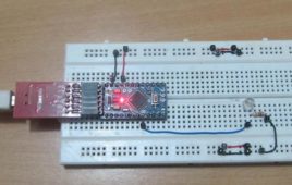
How To Use Digital Input And Digital Output Of Arduino- (Part 2/49)
There is no other tool available which helps in easy prototyping like the arduino does. Any AVR microcontroller based board which follows the standard arduino schematic and is flashed with the arduino boot-loader can be called an arduino board. The arduino can be used as a stand-alone board of which the output or inputs can be taken from the boards or given to the board using convenient connectors.Both digital and analog inputs and outputs are available in all arduino boards.
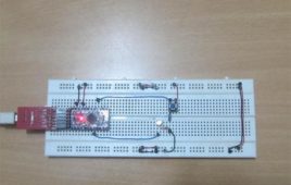
How To Use Analog Input And Analog Output Of An Arduino Board- (Part 3/49)
Even though the microcontrollers are purely digital devices which work on logic0 and logic1 voltages they are commonly found interfaced with analog system or circuits. The microcontroller can read the analog input voltage by sampling it and converting it to their digital values with the help of Analog to Digital Converter (ADC). The microcontroller can also generate an analog voltage on any external device with the help of Pulse Width Modulated (PWM) waves. Most of the microcontrollers have built-in PWM module and ADC modules which helps them in reading analog voltage inputs and generating analog voltage outputs on an external device. Those who have done some basic experiments with the PWM and ADC modules know how complex it is to get them configured, initialized and make them work properly together.
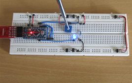
How To Interface 4 Bit LCD With Arduino- (Part 4/49)
Liquid Crystal Display is made use in various kinds of devices from small display screen in calculator to large screens in televisions. There are lots of advantages in using the LCD displays in systems like power efficiency, thin size, low cost etc. LCD based small display modules are normally found in all kinds of embedded devices.The LCD even though looks simple, but it is actually difficult to make it work. The LCD works with voltage pulses only and that with precise timing and voltage levels. Hence special kinds of LCD drivers are developed to drive the LCD. Two or more of this kind of driver ICs together with the LCD screen forms LCD modules which are normally found in embedded systems.
How To Create Custom Characters On LCD Using Arduino- (Part 5/49)

The LCD module is the most common output unit in a microcontroller board. It is very effective since it can display messages, values, clock etc. Special kinds of LCD drivers are used to drive the LCD. Two or more of this kind of driver ICs together with the LCD screen forms LCD modules found in embedded systems. The characters displayed in the LCD modules are actually stored in the internal memory locations of those controllers. They are stored in such a way that they exactly resemble the ASCII table. Whenever the microcontrollers send an ASCII value the LCD controllers displays the ASCII character which has been stored corresponding to that value.The LCD modules can display not only ASCII characters but custom characters also.
How To Use PS2 Keyboard To Store Text In SD Card Using Arduino- (Part 42/49)
The PS2 keyboard uses a simple synchronous serial protocol using only two wires for communication. Due to its simplicity the PS2 keyboards are widely used with simple microcontroller based boards also. The PS2 keyboard always acts as a slave device which can send the equivalent ASCII value of the key which has been pressed to its master device which can be a PC or a microcontroller.The SD memory card comes in large storage capacities from 1 GB up to 32 GB are available. They are used mostly in costly devices like digital camera, media players etc. The SD memory cards are interfaced in high end devices using SD bus which provides very high speed data transfer between the device and the memory card. They also can be interfaced with a device using the low speed and comparatively simple SPI bus and hence they are widely used in microcontroller based system also.
How To Make A Wireless Path Tracking System Using Mouse, XBee And Arduino- (Part 43/49)
The applications of microcontroller are not limited to control simple electrical or electronic device but they are widely used in robotics and automotive industries nowadays. From simple rear view mirror control to complex engine control functions are done by the microcontroller. The microcontroller can even implement to automatically controlling the vehicle without a human driver inside it and such kinds of vehicles are called Unmanned Vehicles (UV). The UVs are commonly used research, military, rescue and agriculture fields. For any UVs the real time tracking of their path is necessary to ensure that they are moving through the proper way.This project demonstrates how it is possible to make a simplest path tracking device for a ground vehicle with the help of optical mouse. This project makes use of an optical mouse which works on PS2 protocol and is interfaced with an Arduino board to read the data from it.
How to Make a Wireless Keyboard Using Xbee with Arduino- (Part 44/49)
The mouse and the Keyboard form the standard input unit for a Personal computer. The QWERT keyboard which is used in the PC comes with a PS2 connector or USB port connector. The PS2 keyboard uses a simple synchronous serial protocol using only two wires for communication. Due to its simplicity the PS2 keyboards are widely used with simple microcontroller based boards also. The PS2 keyboard always acts as a slave device which can send the equivalent ASCII value of the key which has been pressed to its master device which can be a PC or a microcontroller. The ZigBee is the name of a wireless protocol maintained by the IEEE 802.15 standard. This is a protocol specified for wireless Personal Area Network (PAN) using low powered wireless transceivers. There are already wireless transmitter and receiver modules which can do point to point communication.
How to Make Phonecall From GSM Module Using Arduino- (Part 45/49)

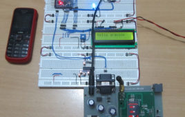
One can use a cell phone with any cellular networks around the globe if the proper SIM card is inserted in it. This is possible because there is some device inside the cell phone which follows a global standard enabling them to connect with different cellular networks. This standard is called Global System for Mobile communications (GSM). The mobile phones have built in GSM modules which then be used by the processor inside the phone to make a call, send or receive message or even connect with the GPRS network. In certain applications the microcontroller based systems has to be connected with the GSM network which will enable a user to control the system by sending messages or making a call. The systems can also send messages to the user to alert or inform about the status of the system running.
How To Make A Call Using Keyboard, GSM Module And Arduino- (Part 46/49)
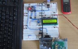
The mobile phones have built –in GSM module which enables them to connect with any cellular network around the globe. The GSM stands for Global System for Mobile communications. In certain applications the microcontroller based systems has to be connected with the GSM network which will enable a user to control the system by sending messages or making a call. The systems can also send messages to the user to alert or inform about the status of the system running. In all such cases a separate GSM module is used rather than using the mobile phones. There are GSM modules available which can do serial communication with microcontroller based systems. The communication is done by sending or receiving AT commands with the GSM module. This particular project demonstrates how to interface a GSM module and dial a call using the standard PS2 keyboard with the help of an Arduino board.
How to Receive SMS Using GSM Module with Arduino- (Part 47/49)
In certain applications the microcontroller based systems has to be connected with the GSM network which will enable a user to control the system by sending messages or making a call. The advantage of using a GSM communication with a system or device is that the user can control the system wirelessly no matter how far it is kept compared to any other wireless communication, provided that both the user and the device should be in a cellular coverage area. The mobile phones have built in GSM modules which then be used by the processor inside the phone to make a call, send or receive message or even connect with the GPRS network. When it comes to a microcontroller based system a separate GSM module is used rather than using a cell phone as such. There are GSM modules available which can do serial communication with microcontroller based systems.
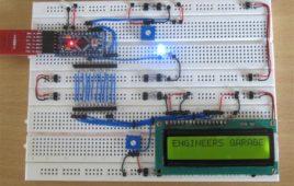
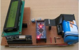
Arduino based Wattmeter
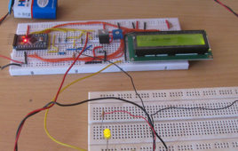
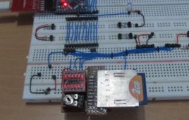
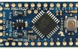
This is a project based on Arduino board which can measure the power consumption of the devices. When we connect this wattmeter on to a device which is in operation, the 16*2 LCD displays its power consumption value in Watts. The project uses an Arduino pro mini board whose ADC feature is used along with the concept of Ohm’s law and Voltage Divider circuit to develop this Wattmeter.
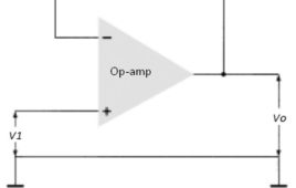
Op-amp Tutorial 1 : Basics, amplifier structure, testing 741 IC
An amplifier is a circuit which can produce an output voltage, which is the product of input voltage with a value called voltage gain. An op-amp (operational amplifier) is a kind of amplifier circuit which can perform an operation (addition, subtraction etc.) on the input voltages, apart from simply amplifying the input. It is an electronic…
Op-amp Tutorial 2 : Features of inverting and non-inverting input and application
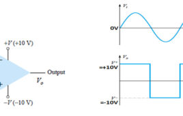
Features of inverting and non-inverting pins The dependency of the output with the inverting and non-inverting pin can be simply explained as below, If the inverting pin is high compared to other pin, the output is negative If the non-inverting pin is high compared to other pin, the output is positive This pecularity of…
Op-amp Tutorial 3 : Astable multivibrator, negative feedback
Astable multivibrator using op amp Astable multivibrator is an electronic device which can continuously shift between its two states with respect to the output. If the output corresponding to one particular state is high, then the output corresponding to the other state is low. This nature of the circuit is useful in producing continuous output…
Op-amp Tutorial 4 : voltage follower, loudness & level indicator, comparato
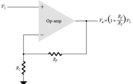
Op amp as a Voltage follower Voltage follower is a negative feedback op-amp amplifier circuit. It acts like emitter follower configuration of transistor based amplifiers. They provide unity gain to the applied input signals. Unity gain means the output voltage will be exactly equal in magnitude with the input voltage. Fig. 1: Circuit Diagram of…
Automatic Meter Reading (AMR) using Arduino
This document discuss about the development and working of a prototype of an AMR (Automatic Meter Reading) using Arduino board. The AMR is now a general term for all kind of meters that can read the data, store the reading and transmit the reading wirelessly on request to another device.There are already water-meters available which allow the interfacing of reed-switch. This project uses a reed-switch along with a rotating magnet to demonstrate the working of AMR.
Unmanned Ground Vehicle (UGV) or Spycar
About this project I’ve developed Unmanned Ground Vehicle (UGV) – a radio controlled 4 wheeler, which have 6 different motions. In this 4 wheeler platform we can mount wireless camera and using the video feedback on a PC, we can drive the vehicle from a distant place. We can control the device through an attractive…
Circular Connectors
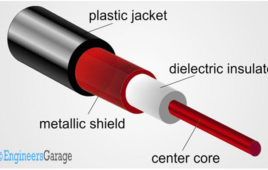
As the name indicates they are circular in shape and the pin contacts are arranged inside the periphery of the circular outer covering. Different[[wysiwyg_imageupload::]]standard and variety of circular connectors are available in which some of them are designed for signal transmission only, some designed for power only and some of them are designed for both signal and power. We will be discussing some of the circular connectors in detail, including RF Coaxial, CPC, DIN and XLR.
Understanding Radio Frequency communication

Wireless communication has been around since 18th century. James Clerk Maxwell first proposed that the electromagnetic waves can be generated and they can travel through free space. Heinrich Rudolf Hertz conducted the experiments in which he demonstrated the generation, transmission and reception of electromagnetic waves which became the basis of Radio Frequency communication. The wireless communication was first introduced as wireless telegraphy in 1890 which soon became popular by the name radio telegraphy. It all started when Guglielmo Marconi developed first wireless telegraph system in 1896. The technology progressed in early 1900s with the introduction of commercial radiotelephony and by 1960s first communication satellites were in space.