Object counters are widely used devices. They are used at different places for different purposes and different usages. They can be used as visitor counter, vehicle counter material/product counter etc. Following are some of the examples where object counters are used.
· In LIFT to count and display number of persons inside the lift at a particular given time
· In any big super market or shopping malls as a visitor counter, to keep track of the number of visitors who have visited the Mall
· On the conveyor belt in the industry to count number of objects passed
· In vehicle parking place to count and display number of vehicles inside the parking lot
Thus the application areas are varied where object counters are used.
The object counter is made up of sensor, counter and display.
· Sensor senses any object that passes in front of it and gives output pulse to the counter
· Counter increments count by one when it gets pulse input from sensor
· Current count is displayed on any type of display like the 7-segment or LCD display
The circuit presented here senses the object when it passes in front of it. The sensor uses IR emitter and detector that detects reflected IR light (from the object) and gives output pulse. This pulse is counted and displayed on 7 segment display or a LCD.
The given circuit is a 2-digit counter so it counts 100 counts from 0 to 99.
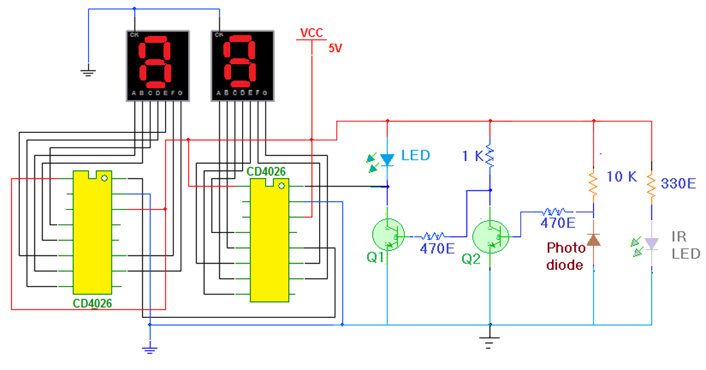
As shown in circuit diagram the major components of circuit are sensor, decade counter cum display driver chip CD4026 and common cathode type 7-segment display.
· The IR LED and photo diode together are used as object sensor. Both are placed near to each other and their direction is also same
· IR LED continuously emits IR light because it’s given 5 V through current limiting resistor
· Photo diode is connected in reverse bias so normally it does not conduct and gives high output
· Its output is given to base input of NPN type transistor Q2 which is connected in switch configuration
· Output of Q2 is given to base input of another NPN transistor Q1 that is also connected in switch configuration
· Finally output of Q1 is given to clock input to first decade counter chip CD4026
·The 7-segment display driver outputs of these chips are connected with respective inputs of 1st 7-segment displays
· When the chip counts from 0 to 9 and resets to 0 again it generates carry out pulse that can be given to next decade counter chip. So this carry output (pin 5) of 1st chip is connected to clock input (pin 1) of 2nd decade counter chip to make cascade connection of 2 decade counter chips and make 2 digit counter
· Again the 7-segment driver outputs of 2nd chip are connected to inputs of 2ndseven segment display as shown
· The common terminals of both 7-segment displays are connected to ground because they are common cathode type displays
· Complete circuit is given power through 5 V supply
Circuit Operation
· IR LED continuously emits IR light
· If there is no object in front of the sensor then IR light is not reflected
· So photo diode does not detect IR light and its output is high
· This high output is inverted two times by two transistors and finally the clock input of 1st counter chip is also high
· But when any object comes in front of sensor, the IR light gets reflected
· This reflected light is detected by photo diode and it gives low output pulse
· The same low output pulse is given to 1st decade counter chip through two transistors
· So counter increments by one digit and it is displayed on 1st 7-segment display
· As counter increments 0 to 9, the 1stdisplay shows values 0 to 9
· On next count 1st counter gives pulse to 2nd counter chip. So the 2nd counter increments
· Thus both counters can togethercounts from 0 to 99 as the objects pass in front of the sensor
Circuit Diagrams
Project Components
Project Video
Filed Under: Electronic Projects
Filed Under: Electronic Projects

Questions related to this article?
👉Ask and discuss on EDAboard.com and Electro-Tech-Online.com forums.
Tell Us What You Think!!
You must be logged in to post a comment.