Engineers Garage

  • Projects and Tutorials
    • Electronic Projects
      • 8051
      • Arduino
      • ARM
      • AVR
      • PIC
      • Raspberry pi
      • STM32
    • Tutorials
    • Circuit Design
    • Project Videos
    • Components
  • Articles
    • Tech Articles
    • Insight
    • Invention Stories
    • How to
    • What Is
  • News
    • Electronic Products News
    • DIY Reviews
    • Guest Post
  • Forums
    • EDABoard.com
    • Electro-Tech-Online
    • EG Forum Archive
  • Digi-Key Store
    • Cables, Wires
    • Connectors, Interconnect
    • Discrete
    • Electromechanical
    • Embedded Computers
    • Enclosures, Hardware, Office
    • Integrated Circuits (ICs)
    • Isolators
    • LED/Optoelectronics
    • Passive
    • Power, Circuit Protection
    • Programmers
    • RF, Wireless
    • Semiconductors
    • Sensors, Transducers
    • Test Products
    • Tools
  • EE Resources
    • DesignFast
    • LEAP Awards
    • Oscilloscope Product Finder
    • White Papers
    • Webinars
  • EE Learning Center
    • Design Guides
      • WiFi & the IOT Design Guide
      • Microcontrollers Design Guide
      • State of the Art Inductors Design Guide
  • Women in Engineering

Accelerometer Controlled Robot without a Microcontroller

By Ganesh Selvaraj

You may have come across many tutorials about accelerometer controlled wireless robot (also known as gesture controlled or glove controlled) but all of them would have a microcontroller. This tutorial teaches you how to make them without using any microcontroller.

Prototype of Microcontroller Less Accelerometer Controlled Robotic Car

Fig. 1: Prototype of Microcontroller Less Accelerometer Controlled Robotic Car

Image: Final Image of Accelerometer Controlled Robot

Components required:

1. Dual axis Accelerometer
 
2. 4x 10k potentiometer
 
3. LM324 OP-AMP IC
 
4. HT12E+HT12D encoder decoder pair
 
5. ASK RF Transmitter and Receiver pair
 
6. L293D Motor Driver IC
 
7. 2x DC motors
 
8. 2x wheels
 
9. Castor wheel
 
10.Chassis
 
11.Breadboards
 
12.Wires


Block Diagram:

Block Diagram of Microcontroller Less Accelerometer Controlled Robotic Car

Fig. 2: Block Diagram of Microcontroller Less Accelerometer Controlled Robotic Car

Accelerometer

 
As the name says, accelerometers are sensors used to sense the proper acceleration in a given axis.
The one I am using is a MMA7361L  three-axis accelerometer module (i.e. x, y and z)  however we will be using only two axes (x and y).


Image showing MMA7361L Accelerometer Module

Fig. 3: Image showing MMA7361L Accelerometer Module


These sensors give analog output proportional to the tilt angle or orientation. We’ll discuss about this later. 


LM324 Op-Amp

LM324 consists of four operational amplifiers which we would use as comparators. One of the inputs of each op-amp would be connected to the accelerometer’s output. And other inputs would be connected to their respective potentiometers which would be tuned later to give the required digital output.

We need four different combinations (For Forward, backward, right and left).
 
Imagine your hand as the accelerometer. The direction your fingers point to is the positive Y direction and opposite to it is the negative Y. Perpendicular to your fingers, X axis exists.
 

Image showing Accelerometer Axis's on a plane with reference to hand

Fig. 4: Image showing Accelerometer Axis’s on a plane with reference to hand

Image showing Accelerometer Axis's in three dimensions with reference to hand

Fig. 5: Image showing Accelerometer Axis’s in three dimensions with reference to hand

These are the four orientations we would be assigning:

Image showing Accelerometer Orientations by hand for navigating robot

Fig. 6: Image showing Accelerometer Orientations by hand for navigating robot

 
Now at normal position (accelerometer parallel to ground), the X and Y outputs of the sensors gives a fixed analog voltage. Read it using a multi-meter. Below are the values I got from my sensor when in normal position and then after tilting the sensor  as shown in the diagram above.
 

VOLTAGE READING

TILT DIRECTION

(in Volts)

NO TILT

FORWARD

BACKWARD

RIGHT

LEFT

X

1.65

NA

NA

2.3

1.1

Y

1.65

2.2

1.1

NA

NA

Now depending on these voltage values, we need to tune the potentiometers to get the correct digital output. Consider the following diagram

Circuit Diagram of MMA7361L Accelerometer and LM324 based circuitry for sensing analog voltage for X axis

Fig. 7: Circuit Diagram of MMA7361L Accelerometer and LM324 based circuitry for sensing analog voltage for X axis

Now depending on these voltage values, we need to tune the potentiometers to get the correct digital output. Consider the following diagram Here Vx is the analog voltage coming from the X output; V1 and V2 are output voltages of the potentiometers. Remember V2 > V1. The circuit follows the below table:

Conditions

Output 1

Output 2

Vx > V2

LOW

HIGH

Vx < V1

HIGH

LOW

V2>Vx>V1

LOW

LOW


So we need to adjust V1, V2 values (using the potentiometer) based on the reading we got and the above table.
 
You can see a demonstration in the video at the end. I connected LEDs to the output pins to see its state.
 
Similarly we do this for Y output also.

Then we would get the below 4-bit output from the LM324 IC:

Tilt Direction

O1

O2

O3

O4

FORWARD

1

0

0

0

BACKWARD

0

1

0

0

RIGHT

0

0

1

0

LEFT

0

0

0

1


For Encoder/Decoder and RF ASK transmitter/Receiver, refer to this tutorial: http://www.engineersgarage.com/electronic-circuits/dc-motor-control-circuit-wireless-rf


Motor Driver

We will be using L293D motor driver which can control two motors bi-directionally. The reason we use a motor driver is because circuits (most of them)/ microcontroller work at a different voltage level when compared to the motor and they cannot provide enough current to the motors. L293D has 4 inputs and 4 output terminals. Here is a table showing the input combinations and corresponding outputs.

INPUTS

MOTOR DIRECTION

ROBOT’S MOTION

I1

I2

I3

I4

LEFT MOTOR

RIGHT MOTOR


1

0

0

1

ANTI CLOCKWISE

CLOCKWISE

FORWARD

0

1

1

0

CLOCKWISE

ANTI CLOCKWISE

BACKWARD

1

0

1

0

ANTI CLOCKWISE

ANTI CLOCKWISE

RIGHT

0

1

0

1

CLOCKWISE

CLOCKWISE

LEFT

Why was a microcontroller needed?

Well if you carefully compare the output table of LM324 IC and the Input table for Motor driver, you would notice a problem.

COMPARATOR OUTPUT

MOTOR DRIVER INPUT

DIRECTION

O1

O2

O3

O4

I1

I2

I3

I4


1

0

0

0

1

0

0

1

FORWARD

0

1

0

0

0

1

1

0

BACKWARD

0

0

1

0

1

0

1

0

RIGHT

0

0

0

1

0

1

0

1

LEFT


Out of 4bits coming from the comparator, only one is high at a time whereas for motor driver, to drive the motors correctly requires two bits to be high and that too in a particular order. That’s where the microcontroller comes into play. We program it in such a way that it takes in the output from the comparator and gives out the correct sequence to the motor driver. Like this:

If (input==1000) output=1001;
Else if (input==0100) output=0110;
Else if (input==0010) output=1010;
Else if (input==0001) output=0101;


How I eliminated the microcontroller?

For this, I simply used an extra IC in place of the microcontroller i.e. a quad 2-input or gate IC. Yeah I am serious, that’s the only extra thing I used. Don’t believe me? Then look at the diagram below. Tally the values of above table with the diagram and equations.
 

Circuit Diagram of Digital Gates used in place of Microcontroller to control movement of Robotic Car

Fig. 8: Circuit Diagram of Digital Gates used in place of Microcontroller to control movement of Robotic Car

At Gate A, I1 = O1 + O3

Gate B, I2 = O2 + O4

Gate C, I3 = O3 + O2

Gate D, I4 = O4 + O1


Quite simple isn’t it?
 
Now that we are done with our designing, let’s move on to the next part.
 

Hardware Setup:

Gather all the parts shown in the image.

Image of Components required for making Robotic Car

Fig. 9: Image of Components required for making Robotic Car


Attach the motors to the chassis and then the wheels to the axle.

Image showing DC Motor attached Metallic Frame of the Robot's Body

Fig. 10: Image showing DC Motor attached Metallic Frame of the Robot’s Body


Image showing wheel attached to DC motor on Robotic Car

Fig. 11: Image showing wheel attached to DC motor on Robotic Car

Use some screws and bolts to attach the castor wheel

Image showing Caster Wheel attached on Front Side of the Robotic Car

Fig. 12: Image showing Caster Wheel attached on Front Side of the Robotic Car


Arrange the transmitter and receiver circuit as per the circuit diagram.

Connect the motors to the motor driver output, and power both the transmitter and receiver. That’s it! You are ready to go!


Image showing Frame of Robotic Car fully assembled with DC Motors and Wheels

Fig. 13: Image showing Frame of Robotic Car fully assembled with DC Motors and Wheels

Arrange the transmitter and receiver circuit as per the circuit diagram.

Prototypes of Transmitter and Receiver Circuits for Robotic Car designed on Breadboards

Fig. 14: Prototypes of Transmitter and Receiver Circuits for Robotic Car designed on Breadboards

Connect the motors to the motor driver output, and power both the transmitter and receiver. That’s it! You are ready to go!

Prototypes of Receiver Circuit attached to Robotic Car

Fig. 15: Prototypes of Receiver Circuit attached to Robotic Car

Circuit Diagrams

Circuit-Diagram-RF-Transmitter-Designed-Accelerometer-Controlled-Microcontroller-Less-Robotic-Car
Circuit-Diagram-RF-Receiver-Designed-Accelerometer-Controlled-Microcontroller-Less-Robotic-Car
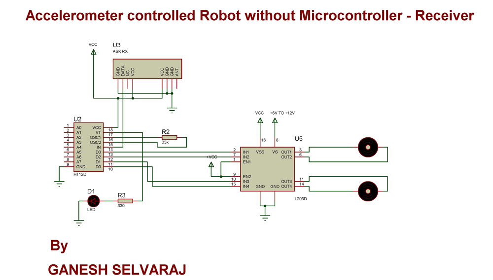
Project Video


Filed Under: Electronic Projects
Tagged With: accelerometer, robot
 

Questions related to this article?
👉Ask and discuss on EDAboard.com and Electro-Tech-Online.com forums.


Tell Us What You Think!! Cancel reply

You must be logged in to post a comment.

HAVE A QUESTION?

Have a technical question about an article or other engineering questions? Check out our engineering forums EDABoard.com and Electro-Tech-Online.com where you can get those questions asked and answered by your peers!


Featured Tutorials

  • Introduction to Brain Waves & its Types (Part 1/13)
  • Understanding NeuroSky EEG Chip in Detail (Part 2/13)
  • Performing Experiments with Brainwaves (Part 3/13)
  • Amplification of EEG Signal and Interfacing with Arduino (Part 4/13)
  • Controlling Led brightness using Meditation and attention level (Part 5/13)
  • Control Motor’s Speed using Meditation and Attention Level of Brain (Part 6/13)

Stay Up To Date

Newsletter Signup

Sign up and receive our weekly newsletter for latest Tech articles, Electronics Projects, Tutorial series and other insightful tech content.

EE Training Center Classrooms

EE Classrooms

Recent Articles

  • What are the battery-selection criteria for low-power design?
  • Key factors to optimize power consumption in an embedded device
  • EdgeLock A5000 Secure Authenticator
  • How to interface a DS18B20 temperature sensor with MicroPython’s Onewire driver
  • Introduction to Brain Waves & its Types (Part 1/13)

Most Popular

5G 555 timer circuit 8051 ai Arduino atmega16 automotive avr bluetooth dc motor display Electronic Part Electronic Parts Fujitsu ic infineontechnologies integratedcircuit Intel IoT ir lcd led maximintegratedproducts microchip microchiptechnology Microchip Technology microcontroller microcontrollers mosfet motor powermanagement Raspberry Pi remote renesaselectronics renesaselectronicscorporation Research samsung semiconductor sensor software STMicroelectronics switch Technology vishayintertechnology wireless

RSS EDABOARD.com Discussions

  • Advice for my disabled son please
  • Very low voltage/power Schmitt trigger?
  • 3D IC Design: Is it possible to stack CPU and FPGA?
  • dc to dc converter sparks when inserting fuse
  • 7 segment display connections

RSS Electro-Tech-Online.com Discussions

  • Pet Microchip scan
  • Disabled son needs advice please
  • Modify a digital clamp ammeter ?
  • Confirming whether this circuit will work
  • How does a blinky/flashing ball work?
Engineers Garage
  • Analog IC TIps
  • Connector Tips
  • DesignFast
  • EDABoard Forums
  • EE World Online
  • Electro-Tech-Online Forums
  • Microcontroller Tips
  • Power Electronic Tips
  • Sensor Tips
  • Test and Measurement Tips
  • 5G Technology World
  • About Us
  • Contact Us
  • Advertise

Copyright © 2022 WTWH Media LLC. All Rights Reserved. The material on this site may not be reproduced, distributed, transmitted, cached or otherwise used, except with the prior written permission of WTWH Media
Privacy Policy | Advertising | About Us

Search Engineers Garage

  • Projects and Tutorials
    • Electronic Projects
      • 8051
      • Arduino
      • ARM
      • AVR
      • PIC
      • Raspberry pi
      • STM32
    • Tutorials
    • Circuit Design
    • Project Videos
    • Components
  • Articles
    • Tech Articles
    • Insight
    • Invention Stories
    • How to
    • What Is
  • News
    • Electronic Products News
    • DIY Reviews
    • Guest Post
  • Forums
    • EDABoard.com
    • Electro-Tech-Online
    • EG Forum Archive
  • Digi-Key Store
    • Cables, Wires
    • Connectors, Interconnect
    • Discrete
    • Electromechanical
    • Embedded Computers
    • Enclosures, Hardware, Office
    • Integrated Circuits (ICs)
    • Isolators
    • LED/Optoelectronics
    • Passive
    • Power, Circuit Protection
    • Programmers
    • RF, Wireless
    • Semiconductors
    • Sensors, Transducers
    • Test Products
    • Tools
  • EE Resources
    • DesignFast
    • LEAP Awards
    • Oscilloscope Product Finder
    • White Papers
    • Webinars
  • EE Learning Center
    • Design Guides
      • WiFi & the IOT Design Guide
      • Microcontrollers Design Guide
      • State of the Art Inductors Design Guide
  • Women in Engineering