The main aim of the project Accident Detection and Messaging System is to inform the Ambulance and Police of the accident site and arrange for necessary steps to control the situation. This system is not only efficient but also worthy to be implemented. . The Accident Detection and Messaging System can be fitted in the vehicle (Ambulance or the Police) and they are informed about any such untoward incident at the go.

Fig. 1: Prototype of Arduino based Car Accident SMS Alert System
Accident Detection and Messaging System execution is simple as the system makes use of GSM and GPS technologies. GPS is used with arduino for taking the coordinates of the site of the accident while GSM is used with arduino for sending the coordinates to cell phones. To make this process all the controls are made using Arduino whereas a LCD is used to display the coordinates.It is assumed that the reader has gone through the project how to get started with the arduino and 16×2 LCD with arduino.

Fig. 2: Block Diagram of Arduino based Car Accident SMS Alert System
How it Works
Accident Detection and Messaging System is easy and the components used are Vibration Sensor, which detects the accident and in turn sends the signals to Arduino. At this point the Arduino takes control and starts collecting the coordinates received from the GPS which are later sent to the Central Emergency Monitoring Station by using the GSM Module.
Circuit Diagram & Programming
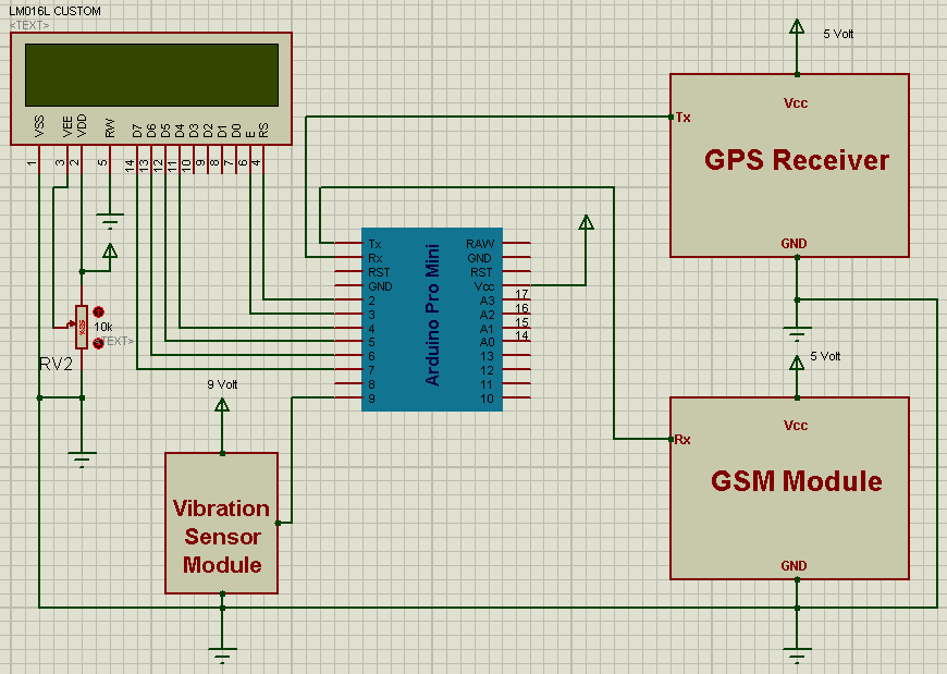
Circuit Diagram Explanation
The circuitry of Accident Detection and Messaging System is similar to vehicle tracking system. The Tx pin of Arduino is directly connected with Rx pin of GSM module and the Rx pin of Arduino is directly connected with the Tx pin of GPS receiver. The output pin of Vibration sensor is connected with pin number 9 of Arduino. The 16×2 LCD’s data pins are connected with the arduino’s pin number 4,5,6,7 and command pin rs and en of LCD are connected with arduino’s pin number 2 and 3. The rw pin of LCD is directly connected with ground. Vibration sensor module sends active low signal when the accident occurs.
Another important aspect of the project is the Power Supply. The Vibration Sensor requires about 9 Volt of DC supply, if we opt for a 5 Volt DC power supply then this circuit will not work properly.

Fig. 3: Image showing Vibration Sensor connected to Arduino Circuit for detecting Car Accident
Programming
The Programming of this project is also similar to that of vehicle tracking system but here an “if” statement is used for sending coordinates when vibration sensor sends low signal to the Arduino.
Before you embark upon building Accident Detection and Messaging System you have to select the same baud rate of GSM and GPS device, but if you are using different baud rate module or device you will face some problem related with the baud rate.
In this system we have used two different baud rates:
4800 bps baud rate for GPS Module and 9600 bps baud rate for GSM Module. When we takes Coordinates from GPS then we have use 4800 bps baud rate and when we have to send Coordinates to control room then we used 9600 bps baud rate.
Components Required
1. .Arduino
2. GSM Module
3. GPS Module
4. Vibration Sensor module
5. 16×2 LCD
6. Power Supply
7. Connecting Wires
Project Source Code
###
#include<LiquidCrystal.h> LiquidCrystal lcd(2,3,4,5,6,7); #define vibrate_sense 9 char str[70]; char *test="$GPGGA"; char logitude[10]; char latitude[10]; int i,j,k; int temp; //int Ctrl+z=26; //for sending msg int led=13; void setup() { lcd.begin(16,2); Serial.begin(4800); pinMode(vibrate_sense, INPUT); pinMode(led, OUTPUT); lcd.setCursor(0,0); lcd.print("GPS Besed Vehicle "); lcd.setCursor(0,1); lcd.print("Tracking System"); delay(3000); } void loop() { if (digitalRead(vibrate_sense)==0) { for(i=18;i<27;i++) //extract latitude from string { latitude[j]=str[i]; j++; } for(i=30;i<40;i++) //extract longitude from string { logitude[k]=str[i]; k++; } lcd.setCursor(0,0); //display latitude and longitude on 16X2 lcd display lcd.print("Lat(N)"); lcd.print(latitude); lcd.setCursor(0,1); lcd.print("Lon(E)"); lcd.print(logitude); delay(100); Serial.begin(9600); Serial.println("AT+CMGF=1"); //select text mode delay(10); Serial.println("AT+CMGS="9610126059""); // enter receipent number Serial.println("Vehicle Accident Happend at Place:"); Serial.print("Latitude(N): "); //enter latitude in msg Serial.println(latitude); //enter latitude value in msg Serial.print("Longitude(E): "); //enter Longitude in Msg Serial.println(logitude); //enter longitude value in msg Serial.print("Help Please"); Serial.write(26); //send msg Ctrl+z=26 temp=0; i=0; j=0; k=0; delay(20000); // next reading within 20 seconds Serial.begin(4800); } } void serialEvent() { while (Serial.available()) //Serial incomming data from GPS { char inChar = (char)Serial.read(); str[i]= inChar; //store incomming data from GPS to temparary string str[] i++; if (i < 7) { if(str[i-1] != test[i-1]) //check for right string { i=0; } } if(i >=60) { break; } } }###
Circuit Diagrams
Project Video
Filed Under: Electronic Projects
Filed Under: Electronic Projects


Questions related to this article?
👉Ask and discuss on Electro-Tech-Online.com and EDAboard.com forums.
Tell Us What You Think!!
You must be logged in to post a comment.