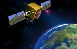
A vehicle tracking system is a technology that tracks and monitors a vehicle’s location in real time. It uses the Global Navigation Satellite System (GNSS) — typically, the Global Positioning System (GPS) — to accurately determine a vehicle’s location. The GPS monitors and relays data to a server through a cellular or satellite network. In…
What are Global Navigation Satellite Systems (GNSS) and how are they used?
Determining a precise location is necessary in several industries for several reasons, including navigation, direction, timing, tracing, and safety. Global Navigation Satellite Systems (GNSS) let users pinpoint exact locations via satellites. GNSS supports critical infrastructure, emergency response, and navigation. GPS, GLONASS, Galileo, and Beidou are the only navigation systems offering global coverage. Regional satellite systems…
What are the top GPS tracker chips of 2023?
The Global Positioning System, better known as GPS, is a satellite-based navigation system that lets users determine the precise location and track movement anywhere on Earth. The system consists of a network of satellites orbiting the Earth, ground stations, and receivers. To learn more about GPS, click here. It’s possible to build a basic GPS…
What is a Global Positioning System (GPS)?
GPS is position and location tracking technology based on the Global Positioning System (GPS) used for determining and tracking the precise location of a person, vehicle, or any other asset. The system uses a GPS receiver that calculates the distance from multiple satellites by measuring the time it takes for the signals to reach the…
Microcontroller-based city locator using GPS and LCD
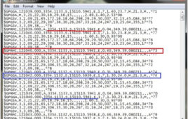
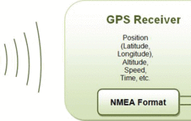
The GPS receiver is used to get accurate geographical location by receiving information from satellites. It receives information from satellites and gives location information in terms of latitude and longitude. It gives latitude and longitudes with accuracy of degree-minute-second. Using this latitude and longitude co-ordinates one can easily trace out the location on entire globe. The GPS receivers have enormous applications.The GPS receiver gives output serially in form of strings with NMEA 0183 protocol. These strings are received serially by host computer or host processor/controller for display or to take any decision or action. The following figure shows the output of GPS receiver on hyper terminal of desktop computer.
Microchip’s enhanced timing grandmaster improves deployment flexibility and security
Infrastructure communication networks — including 5G mobile, utilities, cable, transportation, defense, and data centers — must acquire and maintain signals for precise timing from Global Positioning System (GPS) or other worldwide satellite constellations. These networks require redundant backup systems when Global Navigation Satellite System (GNSS) signals are unavailable. Microchip Technology‘s TimeProvider 4100 Release 2.3 precision-timing grandmaster…
Microchip’s new CSAC provides precise timing accuracy and stability
Advanced military platforms, ocean-bottom survey systems, and remote-sensing applications all require precise timing for mission success. Chip-scale atomic clocks (CSACs) ensure stable and accurate timing even when Global Navigation Satellite Systems (GNSS) time signals are unavailable. Microchip Technology is helping industrial and military system designers to meet this requirement, with its new SA65 CSAC — providing precise…
Traffic Surveillance System using MATLAB and Arduino
In present times increasing Traffic is adding to the big woes of developing cities. The main roads are packed with vehicular traffic on each and every road or a traffic signal (Intersection Points). One comes across the common problem of traffic jams on almost all Traffic Junctions which is even critical if you go to big cities. A lot of time, energies besides precious fuel is wasted just because of these Traffic Jams on the roads.To solve this problem Traffic Cameras are used over Traffic Intersection points. Traffic Cameras capture the image of vehicles in traffic and sends to MATLAB. Here in this project Traffic Surveillance System is demonstrated by way of how the traffic could be controlled over traffic intersection points from the Traffic Control Room. This is a very effective system for Traffic Surveillance.
Microchip integrates monitoring and management platform to protect 5G networks
Today’s 5G wireless infrastructure has more complex, higher-density synchronization needs than previous-generation networks and is highly dependent on the integrity of “live-sky” timing signals from the Global Navigation Satellite System (GNSS). Microchip Technology Inc. announced it has integrated its BlueSky GNSS Firewall with its TimePictra 11 synchronization monitoring and management platform to protect 5G networks…
Accident Detection And Messaging System Using GSM And GPS
The main aim of the project Accident Detection and Messaging System is to inform the Ambulance and Police of the accident site and arrange for necessary steps to control the situation. This system is not only efficient, but also worthy to be implemented. The Accident Detection and Messaging System can be fitted in the vehicle (Ambulance or the Police) and they are duly informed about any such untoward incident immediately.
GPS and GSM based Vehicle Tracking System Using Arduino
This circuit is designed for tracking the location of vehicles. Most oftracking systems are made by using GPS. This is very simple and cheap. Tracking systems are mostly used by fleet operators for tracking a vehicle location, routing and others. This is a very good method for preventing our vehicles from stolen. This tracking system sends us the geographical coordinates and by using these coordinates we can track our vehicle position on electronic maps using internet. By using these tacking systems we can share real time information about transportations. And also can be share real time information or position of trains and buses with passengers. Means passengers can see the real time of arriving busses or trains at the platforms on LCD or on Mobiles.
Latitude & Longitude Display System Using GPS & AVR Microcontroller- (Part 44/46)
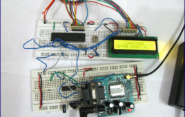
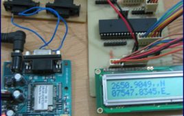
This project is a reference to budding engineers or a helping hand to those who willing to work and interface a GPS Receiver with microcontroller and making their own channel to communicate with satellite, seeking for some useful information from satellite to make a effective and efficient system. Before we check all the details of this project, here is the final implemented circuit diagram of longitude and latitude display system using GPS and AVR microcontroller.
How To Make Arduino As Standalone GPS Receiver With 16×2 LCD- (Part 28/49)
The AVR microcontroller boards which are provided with all the basic circuitry for the operation of the microcontroller which has been flashed with the Arduino boot-loader are called Arduino boards. The Arduino board has all the required circuitary to get the built-in AVR microcontroller running. When it comes to programming the Arduino board anyone who have basic knowledge of c programming can quickly get started with the Arduino IDE. Hence the Arduino forms an easy prototyping platform for both beginners and experts.A microcontroller can communicate with the user by several means including LED display, sound generation, using the serial communication etc. The most commonly found output device in a microcontroller board is an LCD display module.
How To Interface GPS With Arduino- (Part 27/49)
Every single location in the entire globe can be specified in terms of geographical coordinates. The geographical coordinate is a system which specifies any given location on the earth surface as latitude and longitude. There are devices which can read the geographical coordinates of a place with the help of the signals received from a number of satellites orbiting the earth. The system of satellites which helps in the positioning of a place is called Global Positioning System (GPS). The devices which can read the geographical coordinates of a place with the help of at least four GPS satellites are called GPS Receiver or simply GPS module.The GPS module continuously produces a set of data regarding the position of the earth surface where it is situated which includes the current position with respect to the equator of the earth in terms of Latitude and Longitude.
How to interface GPS with PIC18F4550 Microcontroller- (Part 16/25)
Global Positioning System is based on satellite navigation technology. A GPS Receiver provides the accurate location of an object in terms of latitude and [[wysiwyg_imageupload::]]longitude. Accurate time calculation with respect to GMT can also be done by using GPS. For more information on different data obtained through GPS, refer GPS Receivers. Here a PIC microcontroller has been interfaced with a GPS module to extract its position information (location). The main objective here is to find the location of the GPS Receiver in terms of latitude and longitude. The GPS module gives output data in RS232 logic level format. To convert the RS232 logic level into TTL, a line converter MAX232 has been connected between GPS module and PIC18F4550. (Also refer PIC USART) The circuit connection of GPS module with microcontroller is shown in the circuit diagram tab. The latitude and longitude data has been displayed on a 16×2 LCD interfaced to PIC.
How to interface GPS with 8051 Microcontroller (AT89C51)- (Part 36/45)
GPS has become an efficient tool in the field of scientific use, commerce, surveillance and tracking. This project presents a small application based onGlobal [[wysiwyg_imageupload::]]Positioning System. It depicts the use of GPS module/receiver to find latitude and longitude of its location. The data obtained from GPS receiver (GPGGA sentence) is processed by the microcontroller to extract its latitude and longitude values.The GPS Module has been interfaced with AT89C51 and the location values are displayed on a 16×2 LCD interface. The GPS module continuously transmits serial data (RS232 protocol) in the form of sentences according to NMEA standards. The latitude and longitude values of the location are contained in the GPGGA sentence (refer NMEA format). In this program, these values are extracted from the GPGGA sentence and are displayed on LCD.The serial data is taken from the GPS module through MAX232 into the SBUF register of 8051 controller (refer serial interfacing with 8051). The serial data from the GPS receiver is taken by using the Serial Interrupt of the controller.
How to extract details from GPS Receiver using 8051 Microcontroller- (Part 37/45)
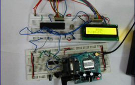
This project is an extension to interfacing GPS with 8051. Here the microcontroller interfaced with GPS module is used to obtain latitude, longitude, time, date and [[wysiwyg_imageupload::]]speed of the receiver. These received values are displayed on a 16×2 character LCD.The GPS module continuously transmits serial data (RS232 protocol) in the form of sentences according to NMEA standards. The latitude, longitude, time, date and speed values of the receiver are contained in the GPRMC sentence as given in the following example (also refer NMEA format for other sentences). In this project, these values are extracted from the GPRMC sentence and are displayed on LCD.Example : $GPRMC,132455.970,A,2651.0145,N,07547.7051,E,0.50,342.76,301010,,,A*64The serial data is taken from the GPS module through MAX232 into the SBUF register of 8051 controller (refer serial interfacing with 8051). The serial data from the GPS receiver is taken by using the Serial Interrupt of the controller. This data consists of a sequence of NMEA sentences from which GPRMC sentence is identified and processed.
GPS Receivers and NMEA Standards
GPS receivers receive almanac data from the satellite and also calculate their position by calculating its distance from then visible satellites and then by using triangulation method to calculate its position. After the data has been received and position has been calculated, the data is configured according to standards set up by NMEA (National…
How to interface GPS with AVR microcontroller (ATmega16)- (Part 43/46)
GPS modem is a device which receives signals from satellite and provides information about latitude, longitude, altitude, time etc. The GPS navigator ismore famous in mobiles to track the road maps. The GPS modem has an antenna which receives the satellite signals and transfers them to the modem. The modem in turn converts the data into useful information and sends the output in serial RS232 logic level format. The information about latitude, longitude etc is sent continuously and accompanied by an identifier string.This article shows how to interface the GPS modem with ATmega16 and extract the location (latitude and longitude) from the GPGGA string and display it on LCD. The connection of GPS modem with AVR microcontroller (ATmega 16) is shown in the circuit diagram. The ground pin of max 232 and serial o/p of GPS modem is made common. Pin2 of MAX232 is connected to pin 3 of GPS modem and pin 3 of max 232 is connected to pin 2 of modem. This type of connection is called a serial cross cable.
GPS : Working , Applications and History
Long before Global Positioning System (GPS) arrived, researchers worked hard to arrive at a feasible solution to aid travellers from getting lost. Earlier, travellers used to rely on elaborate maps to track and monitor the route to their destination. But today, GPS technology has ensured hassle – free trips and increased safety for vehicle owners.GPS works all across the world and in all weather conditions, thus helping users track locations, objects, and even individuals! GPS technology can be used by any person if they have a GPS receiver. The GPS satellites rotate twice a day around the earth in a specific orbit. These satellites transmit signal information to earth.

