Introduction
This is a project based on Arduino board which can measureresistance, diode, continuity[H1] , voltage[H2] , current[H3] , power[H4] , hfe[H5] and capacitance[H6] .The values are displayed onthe 16*2 LCD. The project uses an Arduino pro mini boardwhose ADC feature is used along with the concepts like Voltage divide,Ohms law, RC charging are used to develop this Multi-meter.

Fig. 1: Prototype of Arduino based Digital Multimeter
Description
The entire project can be divided into three basic blocks;
1) Resistance/Diode/Continuity Sensor Unit
2) AC/DC Voltage Sensor Unit
3) DC Current Sensor Unit
4) Power Sensor Unit
5) hfeSensor Unit
6) Capacitance Sensor Unit
7) Processor Unit
8) Display Unit

Fig. 2: Block Diagram of Arduino based Digital Multimeter
The Resistance/Diode/Continuity Sensor, Voltage Sensor, Current Sensor, Power Sensor, Capacitance Sensor and hfeSensor produces output voltages proportional to Resistance/Diode/Continuity, Voltage, Current, Power, Capacitance and hferespectively.
The Processor Unit takes these voltages one by one and calculates the Resistance/Diode/Continuity Sensor, Voltage, Current, Power, Capacitance and hfe. The Processor Unit then sends data to the Display Unit to display the values.
The Display unit takes 4bit data from the Processor Unit and generates a 16*2 display for different measurement values.
1) Resistance/Diode/Continuity Sensor Unit
A basic voltage divider [H7] circuit is used as the Resistance/Diode/Continuity Sensing Unit to provide an output, which is the voltage equivalent of the unknown resistor, diode or continuous path connected as the input. From this output voltage we cancalculate[H8] the value of unknown resistance, detect the diode type or detect a continuous path.
2) AC/DC Voltage Sensor Unit
A basic voltage divider circuit[H9] is used as the AC/DC Sensing Unit to scale down the input DC and AC voltages into a DC voltage in the range of 0 to 5 V. The Processor Unit can read this scaled down voltage and calculate[H10] the actual AC/DC voltages.
3) DC Current Sensor Unit
The Current Sensor in this project is a single low valued resistor through which the current flows to the load device. The basic principle of current measurement is based on the Ohm’s law.
In our project we implement such a resistor in the current flowing path whose resistance value is known. Then we measure the voltage at both the ends of the resistor to calculate[H11] the current flow.
4) Power Sensor Unit
The Power Sensor in this project is a single low valued resistor through which the current flows to the load device. The Voltage across the resistor and the current flow [H12] through the resistor are measured to calculate[H13] the Power consumption of the device.
5) hfe Sensor Unit
The hfe sensor in this project is actually two current sensors[H14] , one of them sense the input current (base current) of the transistor and other one sense the output current (collector current) of the transistor. The current sensors in this project are single low valued resistors through which the current flows to the transistor.
As the current flows through them, voltages get drops across them; we can measure these voltages to calculate[H15] the input current, output current and the hfe.
6) Capacitance Sensor Unit
The Capacitance sensor in this project is an RC discharging circuit in which the unknown capacitor is discharged through a known resistor. While the capacitor discharges the time taken for the capacitor to drop the voltage across it to half the voltage before it starts discharging is measured and from that time value the capacitance is calculated[H16] .
7) Processor Unit
The processor unit in this project is the Arduino board and it uses the ADC module[H17] to read the output voltages from the Sensor Unit. The processor unit then applies an algorithm for calculating the measure resistance, diode, continuity[H18] , voltage[H19] , current[H20] , power[H21] , hfe[H22] and capacitance[H23] .The Processor Unit then sends the data to the Display Unit.
8) Display Unit
The Display Unit is a standard 16*2 LCD on which the Arduino displays the resistance, diode, continuity, voltage, current, power, hfe and capacitance values. The LCD has been wired in four bit mode to reduce the number of output pins of the Arduino board to be used.
Circuit Description

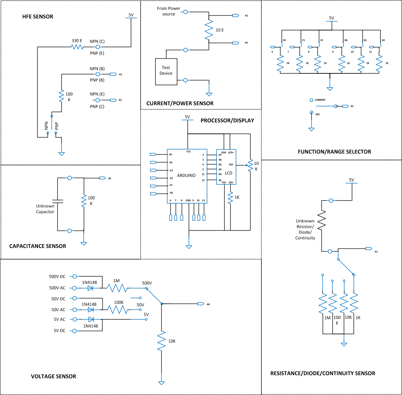
Fig. 3: Circuit Diagrams of various blocks of Arduino based Digital Multimeter
Since the available Analog input channels are multiplexed, array of switches named Function/Range selector are used to select functions and ranges as shown in following table;A value 1 indicates switch closed and the value 0 indicates a switch open.
|
F0 |
F1 |
F2 |
R0 |
R1 |
R2 |
FUNCTION |
RANGE |
|
0 |
0 |
1 |
0 |
1 |
0 |
DC VOLTAGE |
5V |
|
1 |
0 |
50V |
|||||
|
1 |
1 |
500V |
|||||
|
0 |
1 |
1 |
AC VOLTAGE |
5V |
|||
|
1 |
0 |
50V |
|||||
|
1 |
1 |
500V |
|||||
|
0 |
1 |
0 |
0 |
1 |
0 |
RESISTANCE /CONTINUITY |
10K |
|
1 |
0 |
RESISTANCE |
100K |
||||
|
1 |
1 |
1M |
|||||
|
X |
X |
1 |
DIODE |
|
|||
|
0 |
1 |
1 |
X |
X |
X |
CURRENT |
|
|
1 |
0 |
0 |
X |
X |
X |
POWER |
|
|
1 |
0 |
1 |
X |
X |
X |
HFE |
|
|
1 |
1 |
0 |
X |
X |
X |
CAPACITANCE |
|
Code Description
The code reads the analog input channels to calculate the resistance, diode, continuity[H24] , voltage[H25] , current[H26] , power[H27] , hfe[H28] . The code calculates the time elapsed during the capacitor discharge to half its initial voltage and calculates the Capacitance[H29] and displays it. The code identifies the function and range to be displayed by reading the values of Function/Range selector switches.
The code running in the Arduino uses the library function ‘micros()’to get the system time in microseconds. The capacitance value is then displayed on the 16*2 LCD. The code running in the Arduino uses the library function analogRead()to obtain the ADC values and lcd.print()to display the 16*2 LCD.

Fig. 4: Flow Chart of Arduino Code used for sensing various electronic physical quantities like voltage, current and resistance
Note:
The 10 ohm resistor in Ammeter is a high value compared to 0.05 ohm or less precision resistor inside a multi-meter. More current flow more voltage get drop across the resistor, and that voltage drop is proportional to value of resistance. For current values above 500mA measurement, create a low resistance by connecting as many resistances in parallel as possible. Since the ADC of Arduino can read a maximum of 5V only, don’t use a current source with voltage more than 5V.
We have tested the Voltmeter only on maximum 30 V DC.
Project Source Code
###
#include <LiquidCrystal.h>
LiquidCrystal lcd(12, 11, 5, 4, 3, 2);
#define resistance_R50 100000
#define resistance_R500 1000000
#define resistance_V2 10000
#define caliberation_V2 1.1
#define range50_mul (resistance_R50 / resistance_V2) * caliberation_V2
#define range500_mul (resistance_R500 / resistance_V2) * caliberation_V2
#define resistance_Ri 10
#define resistance_Cr 100000
#define resistance_Rb 100000
#define resistance_Re 10
#define resistance_R2 1000
int adc_value = 0;
int voltage_peak_value = 0;
int discharge_voltage_V0 = 0;
int discharge_voltage_V1 = 0;
float voltage_average_value = 0;
float dc_voltage_V0 = 0;
float ac_voltage_V0 = 0;
float dc_voltage_V1 = 0;
float dc_voltage_V2 = 0;
float ac_voltage_V1 = 0;
float dc_current_I0 = 0;
float dc_current_I1 = 0;
float ac_current_I0 = 0;
float dc_power = 0;
float ac_power = 0;
float npn_pnp_hfe = 0;
float capacitance = 0;
unsigned long resistance;
unsigned long sample_count = 0;
unsigned long discharge_time_T0 = 0;
unsigned long discharge_time_T1 = 0;
char fn0 = 6;
char fn1 = 7;
char fn2 = 8;
char rn0 = 9;
char rn1 = 10;
char rn2 = 13;
char function_select [4];
char range_select [4];
void setup()
{
lcd.begin(16, 2);
lcd.print(" EG LABS ");
delay(3000);
pinMode(fn0, INPUT);
pinMode(fn1, INPUT);
pinMode(fn2, INPUT);
pinMode(rn0, INPUT);
pinMode(rn1, INPUT);
pinMode(rn2, INPUT);
}
void loop()
{
function_select [0] = digitalRead(fn0) + '0';
function_select [1] = digitalRead(fn1) + '0';
function_select [2] = digitalRead(fn2) + '0';
function_select [3] = '�';
range_select [0] = digitalRead(rn0) + '0';
range_select [1] = digitalRead(rn1) + '0';
range_select [2] = digitalRead(rn2) + '0';
range_select [3] = '�';
if ( 0 == strcmp (function_select, "001") )
{
//=============================== VOLTAGE ========================================//
voltage_peak_value = 0;
for(sample_count = 0; sample_count < 5000; sample_count ++)
{
adc_value = analogRead(A0);
if(voltage_peak_value < adc_value)
voltage_peak_value = adc_value;
else;
delayMicroseconds(10);
}
dc_voltage_V0 = voltage_peak_value * 0.00488;
ac_voltage_V0 = dc_voltage_V0 / 1.414;
if ( 0 == strncmp (range_select, "01", 2) )
{
lcd.clear();
lcd.setCursor(0, 0);
lcd.print("[R] ");
if (range_select [2] == '0')
lcd.print(" DCV");
else
lcd.print(" ACV");
lcd.setCursor(0, 1);
lcd.print("0-5 ");
if (range_select [2] == '0')
lcd.print(dc_voltage_V0);
else
lcd.print(ac_voltage_V0);
delay(500);
}
else;
if ( 0 == strncmp (range_select, "10", 2) )
{
lcd.clear();
lcd.setCursor(0, 0);
lcd.print("[R] ");
if (range_select [2] == '0')
lcd.print(" DCV");
else
lcd.print(" ACV");
lcd.setCursor(0, 1);
lcd.print("5-50 ");
if (range_select [2] == '0')
lcd.print(dc_voltage_V0 * range50_mul);
else
lcd.print(ac_voltage_V0 * range50_mul);
delay(500);
}
else;
if ( 0 == strncmp (range_select, "11", 2) )
{
lcd.clear();
lcd.setCursor(0, 0);
lcd.print("[R] ");
if (range_select [2] == '0')
lcd.print(" DCV");
else
lcd.print(" ACV");
lcd.setCursor(0, 1);
lcd.print("50-500 ");
if (range_select [2] == '0')
lcd.print(dc_voltage_V0 * range500_mul);
else
lcd.print(ac_voltage_V0 * range500_mul);
delay(500);
}
else;
//=================================================================================//
}
else;
if ( 0 == strcmp (function_select, "010") )
{
//============================= RESISTANCE ========================================//
voltage_average_value = 0;
for(sample_count = 0; sample_count < 10; sample_count ++)
{
adc_value = analogRead(A1);
voltage_average_value = voltage_average_value + adc_value;
delay(10);
}
voltage_average_value = voltage_average_value / 10;
voltage_average_value = voltage_average_value * 0.00488;
if (range_select [2] == '0')
{
lcd.clear();
lcd.setCursor(0, 0);
if ( 0 == strncmp (range_select, "01", 2) )
lcd.print("0-10K: ");
else if ( 0 == strncmp (range_select, "10", 2) )
lcd.print("10-100K: ");
else if ( 0 == strncmp (range_select, "11", 2) )
lcd.print("100K-1M: ");
if (voltage_average_value > 0)
{
if ( 0 == strncmp (range_select, "01", 2) )
resistance = (1000 * (5 - voltage_average_value)) / voltage_average_value;
else if ( 0 == strncmp (range_select, "10", 2) )
resistance = (10000 * (5 - voltage_average_value)) / voltage_average_value;
else if ( 0 == strncmp (range_select, "11", 2) )
resistance = (100000 * (5 - voltage_average_value)) / voltage_average_value;
else;
if (resistance > 10000)
{
lcd.print(resistance / 1000);
lcd.print(" KE");
}
else
{
lcd.print(resistance);
lcd.print(" E");
}
if (resistance < 10)
{
lcd.clear();
lcd.setCursor(0, 1);
lcd.print(" CONTINUITY");
}
else;
}
}
else
{
lcd.clear();
lcd.setCursor(0, 0);
lcd.print("Diode ");
if (voltage_average_value > 0)
{
if ( 0 == strncmp (range_select, "01", 2) )
resistance = (1000 * (5 - voltage_average_value)) / voltage_average_value;
else if ( 0 == strncmp (range_select, "10", 2) )
resistance = (10000 * (5 - voltage_average_value)) / voltage_average_value;
else if ( 0 == strncmp (range_select, "11", 2) )
resistance = (100000 * (5 - voltage_average_value)) / voltage_average_value;
else;
if ((resistance > 145) && (resistance < 165))
lcd.print("Silicon");
else if ((resistance > 60) && (resistance < 80))
lcd.print("Germanium");
else;
}
else;
}
delay(500);
//=================================================================================//
}
else;
if ( 0 == strcmp (function_select, "011") )
{
//================================ CURRENT ========================================//
voltage_average_value = 0;
for(sample_count = 0; sample_count < 10; sample_count ++)
{
adc_value = analogRead(A2);
voltage_average_value = voltage_average_value + adc_value;
delay(10);
}
voltage_average_value = voltage_average_value / 10;
voltage_average_value = voltage_average_value * 0.00488;
dc_voltage_V1 = voltage_average_value;
voltage_average_value = 0;
for(sample_count = 0; sample_count < 10; sample_count ++)
{
adc_value = analogRead(A5);
voltage_average_value = voltage_average_value + adc_value;
delay(10);
}
voltage_average_value = voltage_average_value / 10;
voltage_average_value = voltage_average_value * 0.00488;
dc_voltage_V2 = voltage_average_value;
dc_current_I0 = (dc_voltage_V1 - dc_voltage_V2) / 10;
lcd.clear();
lcd.setCursor(0, 0);
lcd.print(dc_current_I0 * 1000);
lcd.print(" mA");
delay(500);
//=================================================================================//
}
else;
if ( 0 == strcmp (function_select, "100") )
{
//================================= POWER =========================================//
voltage_average_value = 0;
for(sample_count = 0; sample_count < 10; sample_count ++)
{
adc_value = analogRead(A2);
voltage_average_value = voltage_average_value + adc_value;
delay(10);
}
voltage_average_value = voltage_average_value / 10;
voltage_average_value = voltage_average_value * 0.00488;
dc_voltage_V1 = voltage_average_value;
voltage_average_value = 0;
for(sample_count = 0; sample_count < 10; sample_count ++)
{
adc_value = analogRead(A5);
voltage_average_value = voltage_average_value + adc_value;
delay(10);
}
voltage_average_value = voltage_average_value / 10;
voltage_average_value = voltage_average_value * 0.00488;
dc_voltage_V2 = voltage_average_value;
dc_current_I0 = (dc_voltage_V1 - dc_voltage_V2) / 10;
dc_power = dc_current_I0 * dc_voltage_V1;
lcd.clear();
lcd.setCursor(0, 0);
lcd.print(dc_power * 1000);
lcd.print(" mW");
delay(500);
//=================================================================================//
}
else;
if ( 0 == strcmp (function_select, "101") )
{
//================================== HFE ==========================================//
voltage_average_value = 0;
for(sample_count = 0; sample_count < 10; sample_count ++)
{
adc_value = analogRead(A2);
voltage_average_value = voltage_average_value + adc_value;
delay(10);
}
voltage_average_value = voltage_average_value / 10;
voltage_average_value = voltage_average_value * 0.00488;
dc_voltage_V1 = voltage_average_value;
voltage_average_value = 0;
for(sample_count = 0; sample_count < 10; sample_count ++)
{
adc_value = analogRead(A3);
voltage_average_value = voltage_average_value + adc_value;
delay(10);
}
voltage_average_value = voltage_average_value / 10;
voltage_average_value = voltage_average_value * 0.00488;
dc_voltage_V2 = voltage_average_value;
dc_current_I0 = (dc_voltage_V1 / resistance_Re) * 1000;
dc_current_I1 = ((4.99 - dc_voltage_V2) / resistance_Rb) * 1000;
npn_pnp_hfe = dc_current_I0 / dc_current_I1;
lcd.clear();
lcd.setCursor(0, 0);
lcd.print("hfe ");
lcd.print(npn_pnp_hfe);
delay(500);
//=================================================================================//
}
else;
if ( 0 == strcmp (function_select, "110") )
{
//=============================== CAPACITANCE =====================================//
pinMode(18, OUTPUT);
digitalWrite(18, HIGH);
delay(1000);
pinMode(18, INPUT);
discharge_voltage_V0 = analogRead(A4);
discharge_time_T0 = micros();
discharge_voltage_V1 = discharge_voltage_V0 / 2;
while ( discharge_voltage_V1 < analogRead(A4) );
discharge_time_T1 = micros();
capacitance = (discharge_time_T1 - discharge_time_T0) / 0.693;
capacitance = capacitance / resistance_Cr;
lcd.clear();
lcd.setCursor(0, 0);
lcd.print(capacitance);
lcd.print(" uF");
delay(500);
//=================================================================================//
}
else;
}
###
Circuit Diagrams
Project Video
Filed Under: Electronic Projects
Filed Under: Electronic Projects
Log in to leave a comment:
Lost your password?
Don't have an account? Register here