Internet of Things is the fastest growing technology. Like Information Technology revolutionized every field in the early years of twenty first century, the internet of things is about to forward the same legacy. IoT is about to find application everywhere and in everything. The concept of IoT is so scalable, versatile and ubiquitous. In this project, Internet of Things has been used to built a visitor counter which can be monitored online. Such visitor counter can be part of a home automation system or smart home system.
The IoT project developed here is built on Arduino UNO. The Arduino is one of the earliest and most popular prototyping boards. So It is assumed that the reader has gone through the project how to get started with the arduino and done all the things discussed in it.The Arduino is interfaced with ESP8266 Wi-Fi modem to connect with an internet router and access the cloud server. The visitor counter circuit is designed using IR sensors. The Arduino based IoT device simply passes the count of the visitors to the cloud. As the data is updated on the cloud, it can be accessed online using any smart phone or computer.
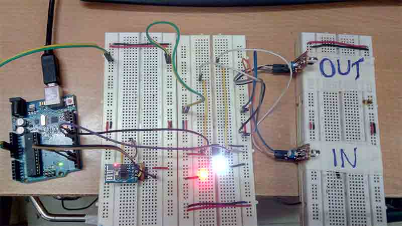
Fig. 1: Prototype of Arduino and ESP8266 based IoT Visitor Counter
Components Required –
The Arduino based IoT device is assembled by the following components –
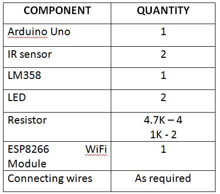
Fig. 2: List of Components required for Arduino and ESP8266 based IoT Visitor Counter
The IR Sensor is designed by assembling the following components in a circuit –
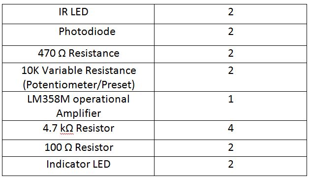
Fig. 3: List of Components required for IR Sensor
Block Diagram –
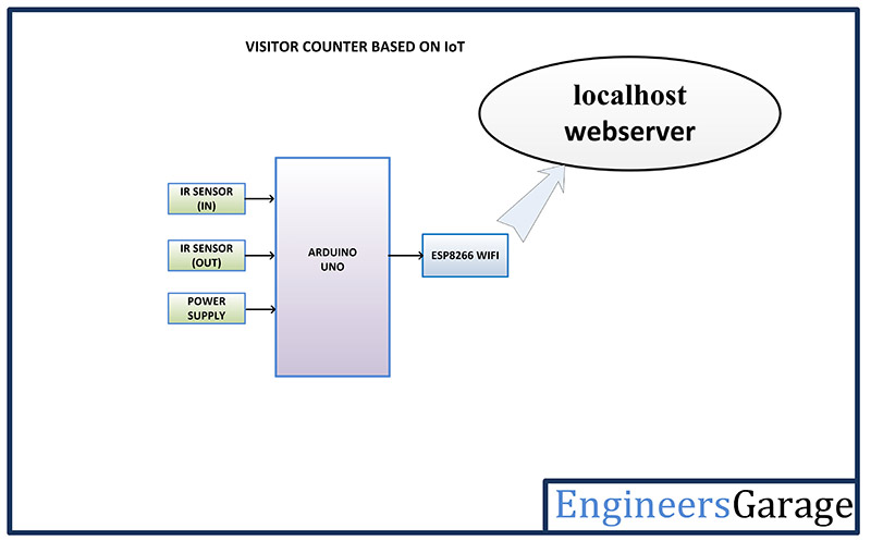
Fig. 4: Block Diagram of Arduino and ESP8266 based IoT Visitor Counter
Circuit Connections –
The IoT device designed for visitor counting is based on Arduino UNO. The Arduino is a commonly used prototyping microcontroller board. It is interfaced with ESP8266 Wi-Fi Modem and custom built IR sensor modules. There are two sensor modules used in the project to track the incoming as well outgoing visitor. This way the actual number of current occupants in the house can be tracked.
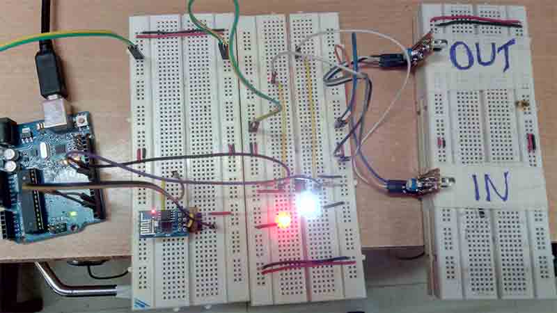
Fig. 5: Image showing circuit connections of Arduino and ESP8266 based IoT Visitor Counter
The IoT device is designed by assembling the following components –
Power Supply – The Arduino is powered by a USB cable. The Wi-Fi modem requires 3.3 V DC which is provided via 3.3 V output of the Arduino. The IR sensor modules require 5V DC which is supplied by the 5V output of the Arduino.
Arduino UNO – The Arduino UNO is ATmega328 based microcontroller board. The board comes with built-in arduino boot loader. It has 14 GPIO pins, 6 PWM pins, 6 Analog inputs and on board UART, SPI and TWI interfaces, an on-board resonator, a reset button, and holes for mounting pin headers. While programming the board, it can be connected to the PC using USB port and the board can runs on USB power. The Arduino UNO has 32 Kb Flash memory, 1 Kb EEPROM and 2 Kb SRAM. The board can be connected to different Arduino Shields for connectivity with Ethernet, Bluetooth, Wi-Fi, Zigbee or Cellular network and it can be connected to most of the IoT platforms. The ATmega328 controller has the following pin configuration –
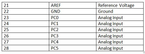
Fig. 6: Table listing pin configuration of Arduino Uno
In this project, two GPIO pins of the Arduino are used to provide serial communication with the ESP8266 modem using software serial and two GPIO are utilized to interface IR sensor modules.
ESP8266 Wi-Fi Modem – The ESP8266 Wi-Fi Module is used to connect the Arduino board with a Wi-Fi router, so that it can access the cloud. It is a self contained SOC with integrated TCP/IP protocol stack that can access to a Wi-Fi network. The ESP8266 is capable of either hosting an application or off loading all Wi-Fi networking functions from another application processor. Each ESP8266 module comes pre-programmed with an AT command set firmware. The module comes available in two models – ESP-01 and ESP-12. ESP-12 has 16 pins available for interfacing while ESP-01 has only 8 pins available for use. The ESP-12 has the following pin configuration –
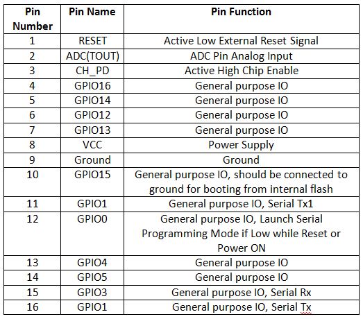
Fig. 7: Table listing pin configuration of ESP8266 ESP-12 Modem
The ESP-01 model is used in the project. The ESP-01 model has the following pin configuration –
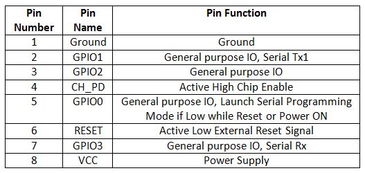
Fig. 8: Table listing pin configuration of ESP8266 ESP-01 Modem
The RESET and VCC pins of the module are connected to the 3.3 V DC while Ground pin is connected to the common ground. The Tx and Rx pins of the module are connected to the 2 and 3 pins of the Arduino UNO.
IR Sensor Module – An IR sensor can measure the heat of an object as well as detects the motion. The infrared sensor is an electronic device that emits IR radiation in order to sense some aspects of the surroundings. Usually in the infrared spectrum, all the objects radiate some form of thermal radiations. These types of radiations are invisible to human eyes but can be detected by an infrared sensor. A passive IR sensor measures only infrared radiation rather than emitting it.
The IR sensor module designed here has an IR emitter and an IR receiver. The emitter is simply an IR LED and the detector is simply an IR photodiode which is sensitive to IR light of the same wavelength as emitted by the IR LED. When IR light falls on the photodiode, the resistance and the output voltage change in proportion to the magnitude of the IR light received.
The sensor module designed here has a digital output. The digital data is expressed in terms of two discrete values – 0 and 1. The smallest unit of digital data is called a ‘bit’. One bit of digital data can only be one of two values – 0 and 1 unlike analog data, where one unit of analog data can hold any value possible. The sensor module must output either HIGH logic or LOW logic so that it could be detected at GPIO pin of the microcontroller. The analog output from the photodiode can be converted into digital data using Analog to Digital Converters (ADC). An Operational amplifier is used here to convert the analog output from photodiode to digital logic of LOW or HIGH.
The IR sensor modules are constructed by the following components –
a) IR Transmitters – The IR LEDs are used as IR transmitters in the circuit. An IR LED is a type of LED which emits light in the Infra-Red frequency range. The infra-red radiations are not visible to the human eye but can be seen by the lenses of a camera. Operationally, IR LEDs are not much different from normal LEDs. They also need a 3V DC for biasing and consume 20 mA current. They also need to be connected with pull-up resistor in a circuit. In the module, IR LEDs are connected with 470 ohm pull-up resistors.
b) IR Receivers – The photodiodes are used as IR receivers in the circuit. A photodiode is a type of diode which gets forward biased when light is incident on it. It has a high resistance when no light is falling on it. When the intensity of light incident on it increases, it starts getting forward biased and current starts flowing through it. So, when light is incident on it, its resistance decreases and there is less voltage drop across it. When light is not incident on it, its resistance increases and there is higher voltage drop across it. The photodiode looks exactly like an LED and may have a dark blue or black film on the outer casing. The photodiodes are used in reverse bias configuration in the circuit.
Variable resistor – The variable resistors are used in the sensor circuit to form a resistive voltage divider. The VCC is applied at the variable resistor side, so the output from the voltage divider is proportional to the resistance of the variable resistor and is inversely proportional to the resistance of the respective photodiode. The use of variable resistor allows calibrating the sensor circuit to properly detect passing of any visitor.
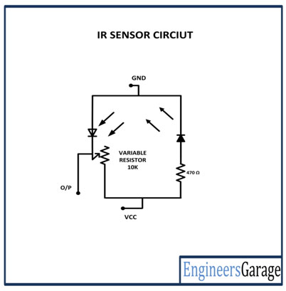
Fig. 9: Circuit Diagram of IR Sensor Module
LM358M OPAM – The LM358M is a general purpose Dual Operational Amplifier (Op-Amp). The LM358M is used as voltage comparator in the circuit. Here it is used to compare two voltages of which one is fixed and the other varies with an environmental parameter. If the parameter controlled voltage is higher than the fixed the voltage, then the IC should give a HIGH output and if it is lower than the fixed voltage, then it should give LOW output. The two types of output (HIGH and LOW) are designed with 5V DC and Ground (0 V) respectively. The OPAM are used as negative voltage comparators in the circuit. The LM358M is an 8-pin IC with following pin configuration –
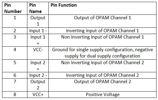
Fig. 10: Table listing pin configuration of LM358M OPAMP IC
The IC is used in single supply configuration in the circuit. For two IR sensor modules, two LM358M ICs are used though each IC provides two OPAM circuits. Any General Purpose Op-amp with similar gain and operating voltages like the LM324M can also be used.
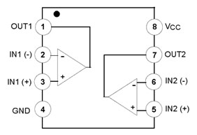
Fig. 11: Pin Diagram of LM358M OPAMP IC
For making the sensor module, the IR transmitters are connected in series with pull-up resistors of 470 ohm between VCC and ground in forward bias configuration. The IR receivers are connected in series with variable resistors between VCC and ground in reverse bias configuration forming a voltage divider circuit. The output from the IR receivers (photodiodes) are drawn from the junction of cathode terminals of the IR receiver and variable resistors. Such one pair of IR receiver and transmitter is connected between VCC and ground to form the IR sensor module. The output from the IR receivers is connected to the pins 9 and 10 of the Arduino UNO via OPAM comparators.
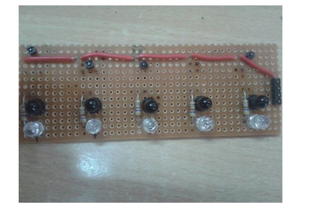
Fig. 12: Image of IR Sensor Array
For proper digital output from the IR receivers, the output from the IR receivers is first connected to the inverting input of the operational amplifier. The non-inverting input of the operational amplifier is provided a reference voltage half the HIGH digital logic (5V for the microcontroller circuit) by connecting two 4.7 K ohm resistors between VCC and ground and connecting the resistive junction with the non-inverting input. Then the output pin of the OPAM is connected to the microcontroller pin. The same is done for both the IR sensors. The operational amplifier is used in the circuit for comparison of the output of IR receiver with the HIGH and LOW digital logic where the reference voltage is set as the half of the HIGH digital logic. So, each OPAM works as a voltage comparator to output a digital logic at the corresponding Arduino pin.
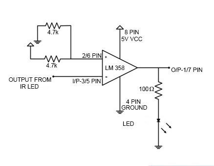
Fig. 13: Circuit Diagram of OPAMP based Negative Voltage Comparator
The OPAM is used as negative voltage comparator in the circuit as the reference voltage is set at the non-inverting input and the input voltage from the IR receiver is applied at the inverting input. In such configuration, when the voltage at the inverting input is lower than the reference voltage at the non-inverting input, the output of the OPAM is HIGH while when the voltage at the inverting input of the OPAM is higher than the reference voltage at the non-inverting input, the output of the OPAM is LOW.
The input from the IR sensor module is drawn from the junction of 10K variable resistor and the IR receiver. When the IR radiation from the IR transmitter is reflected by an obstacle, it is reflected back and absorbed by the IR receiver (Photodiode). This reduces the resistance of the IR receiver, and there is less voltage drop across it. As a result, more voltage is dropped across the variable resistor which is output by the sensor. So there is less voltage output by the sensor module, the voltage at the inverting input is less than the reference voltage resulting in a HIGH output from the OPAM.
When the IR radiation from the IR transmitter is not reflected back, it is gone away and no IR radiation is received to the IR receiver (Photodiode). This increases the resistance of the IR receiver, and there is more voltage drop across it. As a result, less voltage is dropped across the variable resistor and higher voltage is output by the sensor. When there is higher voltage output by the sensor module, the voltage at the inverting input is higher than the reference voltage resulting in a LOW output from the OPAM.
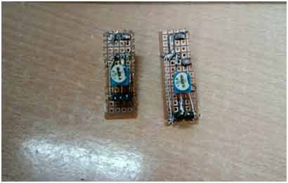
Fig. 14: Image of IR Sensor Modules
There are two sensor modules interfaced with the Arduino. The sensor module interfaced at pin 9 of the Arduino UNO is installed to detect an incoming visitor while the sensor module interfaced at pin 10 is installed to detect an outgoing visitor.
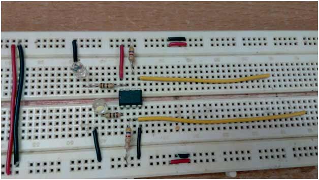
Fig. 15: Image of OPAMP Circuit used with IR Sensors
How the circuit works –
When the Arduino based IoT device is powered on, it starts searching for a Wi-Fi Access Point. If a Wi-Fi access point is available, the Arduino obtains the IP address if required and connect with the Wi-Fi point. The name and password of the Wi-Fi access point are hard-coded in the Arduino sketch. The initialization of the Wi-Fi connection is done within the setup() function of the Arduino Sketch which runs once the board is powered on.
The setup of Wi-Fi connection is run by passing AT commands to the ESP8266 Wi-Fi modem. The modem is connected to GPIO pins of the Arduino which are configured as UART transmitter and receiver pins by using software serial library. The Wi-Fi is initialized by passing the following AT commands to ESP module –
AT : This command is passed to check if modem is functioning properly.
AT+CWMODE=3 : This command is passed to set the Wi-Fi mode to both AP as well as Station mode.
AT+CWQAP: This command is passed to disconnect from any AP (Access Point) if the modem is connected to.
AT+RST: This command is passed to reset the modem.
After reset, the modem check IP addresses of the available access points. The ESP modem can connect with the access point whose SSID and Password are hard-coded in the Arduino Sketch. The following AT command is passed to connect with the Access Point –
AT+CWJAP
Once the modem is connected to an access point, it obtains IP address by executing the following command –
AT+CIFSR: This command is used to obtain IP address of ESP module as an client.
The IP address is stored in a string and acknowledged to the Arduino board. Now the following AT commands are passed to the ESP module –
AT+CIPMUX=1: This command is passed to enable multiple connections.
AT+CIPSERVER=1,80: This command is passed to create a server at port 80.
The GPIO pins of the Arduino interfacing the IR sensor modules are set to digital input in the same setup function. The Arduino now starts detecting logic at the IR sensor interfaced pins. If the digital logic at the pin interfaced to IR module installed at the entrance goes LOW, the number of occupants is increased by one and if the digital logic at the pin interfaced to IR module installed at the exit goes LOW, the number of occupants is decreased by one. The number of occupants is updated to a webpage running on the local server.
The local server is a PC or laptop connected to the same Wi-Fi access point and running local host. A webpage is created by the Arduino Sketch and sent with the updated number of occupants to the local server.
Programming Guide –
The Arduino sketch running on the IoT device manages to pass the AT commands to the ESP module for connecting and configuring the Wi-Fi connection, increase or decrease the number of occupants as a variable by detecting logic from the IR sensors, create a webpage and push the HTML content creating webpage to the local web server.
The Arduino Sketch begins with importing required libraries and declaration of the variables holding data for the tracking number of visitors, IP address of Wi-Fi Access Point and HTML content for the webpage.

Fig. 16: Screenshot of Initialization in Arduino Code for IoT Visitor Counter
The setup() function is called in which baud rate for the serial communication with the Wi-Fi modem is set. The WiFi mode and network connectivity is established using the AT commands with some delays. The delay should be given according to time it takes to connect with the network by calling the wifi_init() function.
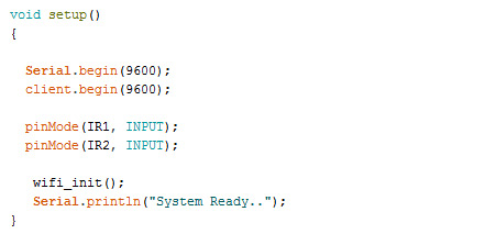
Fig. 17: Screenshot of Setup Function in Arduino Code for IoT Visitor Counter
The loop() function is called which runs infinitely. In this function the digital logic at the IR sensor modules is detected and stored in the initialized variables. The functions to create HTML content for the webpage with updated number of occupants and to send the webpage to the local web server are called.

Fig. 18: Screenshot of Loop Function in Arduino Code for IoT Visitor Counter
Check out the Arduino Sketch from the code section to try it out.
This project is developed as part of a smart home system. Here, the current number of occupants can be checked online on a local server anytime. Any device – PC, laptop or smart phone can be configured to work as local server.
Project Source Code
###


//Program to


/*=========================================================================*/

/*Standard Library                                                         */

/*=========================================================================*/

#include<SoftwareSerial.h>


/*=========================================================================*/

/*Variable Initialization for webserver                                    */

/*=========================================================================*/

SoftwareSerial client(2,3); //RX, TX

int x=0;

int i=0, k=0;

String IP = "";

char temp1 = '0';

String webpage = "";

String readString;

boolean No_IP = false;

int value = 0;   //22

String data = "<p>IoT Based Visitor Counter<p>";

String dat  = "<p>Persons count inside<p>";


/*===========================================================================*/

/* PIN-map.                                                                  */

/*===========================================================================*/

#define IR1                      9       /* digital pin input for ir sensor  */

#define IR2                     10       /* digital pin input for ir sensor  */

#define MAX_NUMB                40


/*===========================================================================*/

/* Functions and variables for IR sensor                                     */

/*===========================================================================*/

int IR1_out = HIGH; /* Avoiding initial false detections.    */

int IR2_out = HIGH; /* Avoiding initial false detections.    */

int counter = 0;


/*============================================================================*/

/*Function definition for incrementing the count                              */

/*============================================================================*/

void increaseAndDisplay()

{

  counter++;

  if(counter > MAX_NUMB) {

    counter = 1;

  }

  value = counter;

}


/*============================================================================*/

/*Function definition for decrementing the count                              */

/*============================================================================*/

void decreaseAndDisplay()

{

  if(counter) {

    counter--;

    value = counter;

  }

}


/*============================================================================*/

/*Function definition to check the IP to be connected                         */

/*============================================================================*/

void check4IP(int t1)

{

  int t2=millis();

  while(t2+t1>millis())

  {

    while(client.available()>0)

    {

      if(client.find("WIFI GOT IP"))

      {

        No_IP=true;

      }

    }

  }

}


/*============================================================================*/

/*Function definition to get IP address to network connected                  */

/*============================================================================*/

void get_ip()

{

  IP="";

  char ch=0;

  while(1)

  {

    client.println("AT+CIFSR");

    while(client.available()>0)

    {

      if(client.find("STAIP,"))

      {

        delay(1000);

        Serial.print("IP Address:");

        while(client.available()>0)

        {

          ch=client.read();

          if(ch=='+')

          break;

          IP+=ch;

        }

      }

      if(ch=='+')

      break;

    }

    if(ch=='+')

    break;

    delay(1000);

  }

  Serial.print(IP);

  Serial.print("Port:");

  Serial.println(80);

}


/*============================================================================*/

/*Function definition that gets command and makes wifi connection             */

/*============================================================================*/

void connect_wifi(String cmd, int t)

{

  int temp=0,i=0;

  while(1)

  {

    Serial.println(cmd);

    client.println(cmd);

    while(client.available())

    {

      if(client.find("OK"))

      i=8;

    }

    delay(t);

    if(i>5)

    break;

    i++;

  }

  if(i==8)

  Serial.println("OK");

  else

  Serial.println("Error");

}


/*============================================================================*/

/*Function definition which has AT commads and function call to connect_wifi()*/

/*============================================================================*/

void wifi_init()

{

      connect_wifi("AT",100);

      connect_wifi("AT+CWMODE=3",100);

      connect_wifi("AT+CWQAP",100);

      connect_wifi("AT+RST",5000);

      check4IP(5000);

      if(!No_IP)

      {

        Serial.println("Connecting Wifi....");

        connect_wifi("AT+CWJAP="EngineersGarage","egP@$$w0rd?"",7000);         //provide your
WiFi username and password here

     // connect_wifi("AT+CWJAP="vpn address","wireless network"",7000);

      }

      else

        {

        }

      Serial.println("Wifi Connected");

      get_ip();

      connect_wifi("AT+CIPMUX=1",100);

      connect_wifi("AT+CIPSERVER=1,80",100);

}


void sendwebdata(String webPage)

{

    int ii=0;

     while(1)

     {

      unsigned int l=webPage.length();

      Serial.print("AT+CIPSEND=0,");

      client.print("AT+CIPSEND=0,");

      Serial.println(l+2);

      client.println(l+2);

      delay(100);

      Serial.println(webPage);

      client.println(webPage);

      client.print("n");

      while(client.available())

      {

        //Serial.print(Serial.read());

        if(client.find("OK"))

        {

          ii=11;

          break;

        }

      }

      if(ii==11)

      break;

      delay(100);

     }

}


/*============================================================================*/

/*Setup() function that runs first*/

/*============================================================================*/

void setup()

{


  Serial.begin(9600);

  client.begin(9600);


  pinMode(IR1, INPUT);

  pinMode(IR2, INPUT);


   wifi_init();

   Serial.println("System Ready..");

}


/*============================================================================*/

/*loop() which is main function that has function call for all function       */

/*============================================================================*/

void loop()

{

  IR1_out = digitalRead(IR1);

  IR2_out = digitalRead(IR2);

  if(IR1_out == LOW) {

    increaseAndDisplay();

  }

  if(IR2_out == LOW) {

    decreaseAndDisplay();

  }


  k=0;

  Serial.println("Please Refresh your Page");

  while(k<1000)

  {

    k++;

   while(client.available())

   {

    if(client.find("0,CONNECT"))

    {

      Serial.println("Start Printing");

      Send();

      Serial.println("Done Printing");

      delay(1000);

    }

  }

  delay(1);

 }

}


/*============================================================================*/

/*Function definition to post the data to webpage*/

/*============================================================================*/

void Send()

{

      webpage = "<h1>Welcome to Engineers Garage</h1><body bgcolor=bae3f2>";

      sendwebdata(webpage);

      webpage = data;

      webpage+=dat;

      webpage+=value;

      sendwebdata(webpage);

      delay(1000);

     client.println("AT+CIPCLOSE=0");

}

###
Circuit Diagrams
Project Video
Filed Under: Electronic Projects, IoT
Filed Under: Electronic Projects, IoT


Questions related to this article?
👉Ask and discuss on Electro-Tech-Online.com and EDAboard.com forums.
Tell Us What You Think!!
You must be logged in to post a comment.