Every single location in the entire globe can be specified in terms of geographical coordinates. The geographical coordinate is a system which specifies any given location on the earth surface as latitude and longitude. There are devices which can read the geographical coordinates of a place with the help of the signals received from a number of satellites orbiting the earth. The system of satellites which helps in the positioning of a place is called Global Positioning System (GPS). The devices which can read the geographical coordinates of a place with the help of at least four GPS satellites are called GPS Receiver or simply GPS module.
The GPS module continuously produces a set of data regarding the position of the earth surface where it is situated which includes the current position with respect to the equator of the earth in terms of Latitude and Longitude. This data can be decoded and printed into the readable format with the help of a microcontroller only. In this project the data regarding the geographical coordinate is extracted from the GPS output with the help of the Arduino. The Arduino can be used as a stand-alone board of which the output or inputs can be taken from the boards or given to the board. They can communicate using standard communication ports like USART, TWI, SPI etc. which enables them to be connected with various kinds of devices. The Arduino board is designed for easy prototyping and the IDE used for coding is very simple and provides so many libraries for interfacing with common external devices.
The GPS module used in this project is SR-91 based GPS module which can communicate the data regarding the current location to a PC or microcontroller through the serial port. The image of the GPS module used for this project is shown below;

Fig. 2: SR-91 based GPS Module for serial communication
The arduino board used in this project is the arduino pro-mini board and the IDE version of the arduino is 1.0.3 for windows. The image of the arduino pro-mini board and the arduino IDE are shown below;

Fig. 3: Typical Arduino Pro-Mini Board

Fig. 4: Arduino IDE Software Window
Since the arduino pro-mini board has no circuitary for interfacing it with the serial port or the USB port of the PC, an external USB to TTL converter board is required to connect it with the PC. This hardware helps in programming the arduino board and also helps in the serial communication with the USB port of the PC.

Fig. 5: External USB to TTL converter board for programming Arduino and serial communication
It is assumed that the reader has gone through the project getting started with arduino and tried out all the things discussed there.
The Arduino read the serial data from the GPS module using the serial communication functions provided by the Arduino library. The functions like Serial.begin() which helps to initialize the serial port with a given baud rate, Serial.write() to send a data to the serial port, Serial.available() and Serial.read() functions to read data from the serial port are used in this project and they are already discussed in previous projects on on how to do serial communication with the Arduino, how to send and receive serial data using arduino and how to do serial debugging with the Arduino.
Using the function Serial.read() the Arduino continuously reads the data from the GPS module, looking for Latitude-Longitude details. The GPS send the data in standard NMEA format which consist of the real time data regarding the current position. The format includes so many sentences and among them one particular sentence referred to as “Global Positioning System Fix Data” is extracted to read the Latitude Longitude.
The screenshot of the “Global Positioning System Fix Data” among the NMEA format data output from the GPS module is shown in the following image;

Each sentence has a sentence identifier, actual data separated by commas and a check sum which has to be extracted to make it in readable format. The details of the sentence “Global Positioning System Fix Data” is given in the following table;
|
NAME |
EXAMPLE DATA |
DESCRIPTION |
|
Sentence Identifier |
$GPGGA |
Global Positioning System Fix Data |
|
Time |
170834 |
17:08:34 Z |
|
Latitude |
4124.8963, N |
41d 24.8963′ N or 41d 24′ 54″ N |
|
Longitude |
08151.6838, W |
81d 51.6838′ W or 81d 51′ 41″ W |
|
Fix Quality: |
1 |
Data is from a GPS fix |
|
Number of Satellites |
05 |
5 Satellites are in view |
|
Horizontal Dilution of Precision (HDOP) |
1.5 |
Relative accuracy of horizontal position |
|
Altitude |
280.2, M |
280.2 meters above mean sea level |
|
Height of geoid above WGS84 ellipsoid |
-34.0, M |
-34.0 meters |
|
Time since last DGPS update |
blank |
No last update |
|
DGPS reference station id |
blank |
No station id |
|
Checksum |
*75 |
Used by program to check for transmission errors |
Fig. 6: Details of sentence “Global Positioning System Fix Data”
To simply output the Latitude-Longitude coordinate using the Arduino, the code written for the project continuously reads the characters from the GPS module and check them for two consecutive ‘G’ s, so as to get the sentence starting with $GPGGA. Once the message is found the code seeks through the message, skipping the letters till the first two commas and printing the rest as the Latitude, till the following comma. The code again skips the characters till it found another comma and the following letters till the next comma are printed as Longitude.
The code uses do-while loop to look for particular characters or set of characters, as an example to ignore all the letters till two consecutive ‘G’s the code uses the following statements;
//==================== searching for “GG” ===================//
do
{
do
{
while ( !Serial.available() );
} while ( ‘G’ != Serial.read() );
while(!Serial.available());
} while ( ‘G’ != Serial.read() );
//==================== searching for “GG” ===================//
Similarly to ignore all the letters till a comma is received the code uses the following statements;
//=======================================//
do
{
while ( !Serial.available() );
} while ( ‘,’ != Serial.read() );
//=======================================//
When the coding is finished one can verify and upload the code to the Arduino board as explained in the project how to get started with the Arduino . The Arduino board can then be connected to the PC using USB to TTL converter board and geographical coordinates can be read using any serial monitoring software or using the Arduino IDE’s serial monitoring software itself as explained in the project how to do serial debugging with the Arduino.
Project Source Code
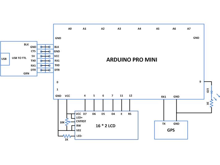
###


/*============================ EG LABS ===================================//


 Demonstration on how to use PS2 MOUSE with an arduino board


 The circuit:

 LCD:

 * LCD RS pin to digital pin 12

 * LCD Enable pin to digital pin 11

 * LCD D4 pin to digital pin 7

 * LCD D5 pin to digital pin 6

 * LCD D6 pin to digital pin 5

 * LCD D7 pin to digital pin 4

 * LCD R/W pin to ground

 * 10K resistor:

 * ends to +5V and ground

 * wiper to LCD pin 3


LED:

 * LED anode attached to digital output 9

 * LED cathode attached to ground through a 1K resistor


 GPS:

 TX PIN OF GPS TO RX1 PIN OF ARDUINO

 SHORT THE GROUND PINS OF ARDUINO AND GPS


============================== EG LABS ===================================*/


#include <LiquidCrystal.h>


// initialize the library with the numbers of the interface pins

LiquidCrystal lcd(12, 11, 7, 6, 5, 4);


// give the pin a name:

int led = 9;

// incoming serial byte

int inByte = 0;


void setup()

{

  // set up the lcd's number of columns and rows:

  lcd.begin(16, 2);

  lcd.print("ENGINEERS GARAGE");

  lcd.setCursor(0, 1);

  lcd.print(" GPS  INTERFACE ");


  // initialize the led pin as an output.

  pinMode(led, OUTPUT);

  // start serial port at 9600 bps

  Serial.begin(4800);

  // wait for a while till the serial port is ready

  delay(100);


  // send the initial data once //

  Serial.print('n');

  Serial.print("       EG LABS    ");

  Serial.print('n');

  Serial.print('r');

  Serial.print(" GEOGRAPHICAL CORDINATES");

  Serial.print('n');

  Serial.print('r');

  Serial.print('n');


  digitalWrite(led, HIGH);

}


void loop ()

{

//==================== searching for "GG" ===================//

    do

    {

        do

        {

            while ( !Serial.available() );

        } while ( 'G' != Serial.read() );                    // reading a character from the GPS


        while(!Serial.available());

    } while ( 'G' != Serial.read() );

//==================== searching for "GG" ===================//


//============== seeking for north cordinate ==============//

    do

    {

        while ( !Serial.available() );                       // reading a character from the GPS

    } while ( ',' != Serial.read() );


    do

    {

        while ( !Serial.available() );                       // reading a character from the GPS

    } while ( ',' != Serial.read() );

//============== seeking for north cordinate ==============//


//============== printing the north cordinate ===============//

    Serial.print(" N: ");

    do

    {

        while ( !Serial.available() );

        inByte = Serial.read();                              // reading a character from the GPS

        Serial.write ( inByte );                             // printing the Latitude

    } while ( ',' != inByte );

//============== printing the north cordinate ===============//


//============== seeking for east cordinate ==============//

    do

    {

        while ( !Serial.available() );                       // reading a character from the GPS

    } while ( ',' != Serial.read() );

//============== seeking for east cordinate ==============//


//============== printing the east cordinate ===============//

    Serial.print(" E: ");

    do

    {

        while ( !Serial.available() );

        inByte = Serial.read();                              // reading a character from the GPS

        Serial.write ( inByte );                             // printing the Longitude

    } while ( ',' != inByte );

//============== printing the east cordinate ===============//

    Serial.println();


    delay ( 1000 );

}

###
Circuit Diagrams
Project Components
Project Video
Filed Under: Arduino
Filed Under: Arduino

Questions related to this article?
👉Ask and discuss on EDAboard.com and Electro-Tech-Online.com forums.
Tell Us What You Think!!
You must be logged in to post a comment.