In the previous tutorial, we covered the AT commands that are supported by a SIM900 GSM-GPRS modem. We’ve already discussed how to interface a SIM900A GSM-GPRS modem with Raspberry Pi, Arduino, as well as other microcontrollers and desktop computers. Now, it’s time to use this modem to make and receive calls, and send and receive SMS.
In this tutorial, we’ll demonstrate voice call and SMS messaging using a SIM900A with Raspberry Pi (RPi) and a desktop computer.
Communicating with a GSM-GPRS modem using Python
We’ve previously learned about serial universal asynchronous receiver/transmitter (UART) communication using RPi’s serial TTL port.
Simply interface the GSM modem with RPi’s serial TTL port and open a serial communication port with the modem using the serial.Serial() method. Next, you can send the AT commands to the modem using the serial.write() method and receive a response from the AT commands using the serial.read() method.
The response from the modem can be stored in a variable and printed on the console the using print() method. It’s also possible to design a GUI application using the TTK library and a text editor so the data is sent and received over a serial port — and shown within a Python application.
In fact, Python is platform-independent and can be used to set up serial communication on any device and any other platform (i.e. not just RPi’s Linux platform but also others such as Win32 and macOS).
On a desktop system, the modem can be interfaced using a USB-serial board. To do so, first figure out the port name where the GSM modem is interfaced with the desktop, via the USB interface. We’ve covered how to find a serial port name on a desktop here.
Typically, the modem communicates at 9600 bps baud rate and 8N1 UART data encoding. The modems are designed to auto-detect the baud rate. While the data encoding scheme remains 8N1, the maximum 115200 bps baud rate can be used to communicate with the modem.
Booting the SIM900A GSM-GPRS modem
To begin, we must prepare the GSM modem for cellular communication. Insert a SIM card into the SIM cardholder of the SIM900A modem. The modem is similar to a mobile phone and requires a SIM card to connect with a cellular network.
Most of the modems have SIM cardholders for Mini SIM (2FF form factor). However, Micro SIM (3FF form factor) and Nano SIM (4FF form factor) can also be plugged in so long as the SIM contacts touch the cardholder pins properly.
Next, turn on the GSM modem by connecting the modem to a power adaptor (5V-12V, 2A). The modem’s status LED or Network LED will start blinking. It typically blinks at a faster rate while the modem connects to the mobile network. Once the modem is connected to the subscribed communication service provider (CSP), it blinks every three seconds. It may take up to a minute for the modem to boot (just like a mobile phone boot) and connect with a subscribed mobile network.
If you ring the plugged-in SIM, the modem will start ringing via the buzzer and flash the ring indicator LED on it. This confirms the modem is working. In fact, when you call the SIM number, the call is automatically picked up by the modem after a few rings. And if you connect a speaker and microphone to the modem, you can speak to and receive calls on the plugged-in SIM. So, the microphone and speaker input are actually on the modem.
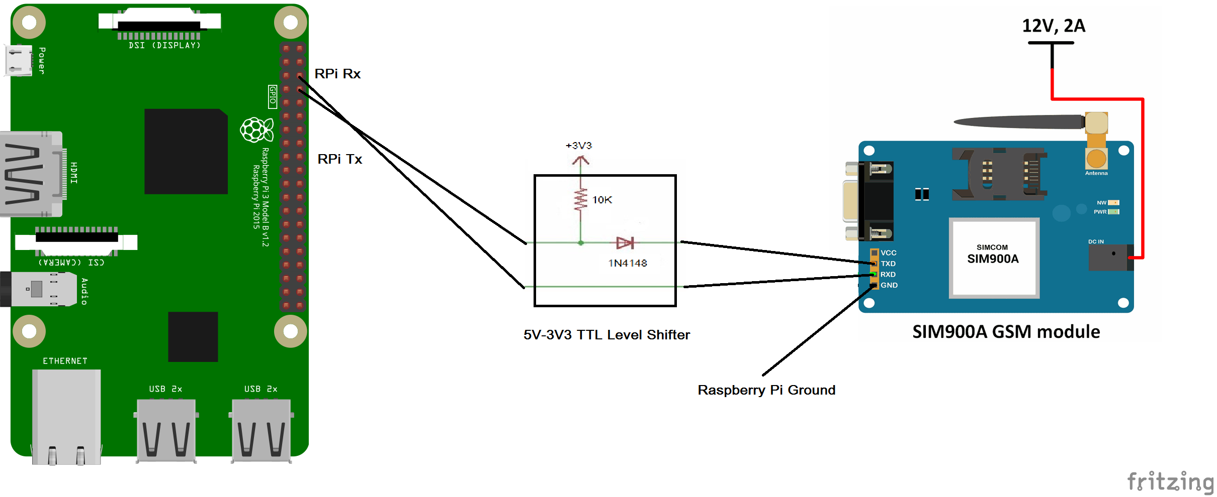
Interfacing SIM900A with RPi
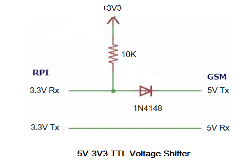
The SIM900A modem is a 5V device and Raspberry Pi is s 3.3V single-board computer. We cannot directly interface the TTL serial port of the SIM900 modem with RPi’s serial TTL port.
If you directly connect the serial ports of modem and RPi, it will transmit the serial data to the modem because the 5V modem can tolerate 3.3V UART voltages. But when you try to receive data from the modem on RPi, the 5V UART signals from modem can damage or destroy RPi’s serial receiver pin.
To be safe, let’s use a 5V to 3.3V TTL Logic Shifter. A simple 5V-to-3V3 logic shifter can be designed using 1N4148 diode as shown in this circuit diagram:
Alternatively, you can use a 2, 4, or 8-channel level switching I/O module. This is an 8-channel level switching bidirectional I/O module:

Next, connect the modem’s Rxd, Txd, and ground pins with those of RPi via the level-switching circuit or I/O module. Now, you are ready to communicate with the modem over the serial port.
Making a call from Raspberry Pi
To enable serial communication with the modem on RPi, you must import the serial, RPi.GPIO, os, and time libraries. The os and time library are necessary to use the sleep() function, which ensures RPi awaits responses from the modem.
Begin by setting the pin numbering system to the board numbers and access RPi’s serial TTL port using the serial.Serial() method. The port name on Raspberry Pi is /dev/serial0. Alternatively, the port name can be /dev/ttyS0 or /dev/ttyAMA0 — use whichever one is the primary UART on the respective Raspberry Pi.
Send the AT command “AT” to the modem using the serial.write() method to check communication with it. Read the response from the modem using the serial.read() method and print it to the console using the print() method or to a GUI interface. The modem will respond “OK” if it’s properly working and connected to Raspberry Pi.
- To make a call, send an “ATD<Mobile-Number>” command to the modem
- To end the call, send an “ATH” command to the modem
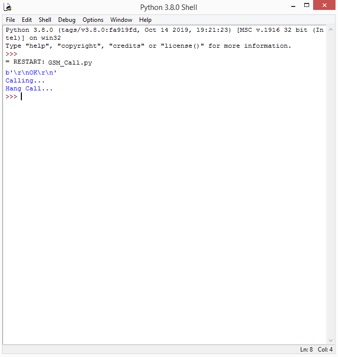
The Python script that’s shown below successfully makes a call on a number and ends the call after 30 seconds. The AT commands are passed as bytes to the modem and the ‘\r’ escape sequence is used to pass the command-line enter. You can also connect a microphone and speaker with the modem. Previously, we hacked an earphone so voice calls could be received on the GSM-GPRS modem.
import serial
import os, time
import RPi.GPIO as GPIO
GPIO.setmode(GPIO.BOARD)
port = serial.Serial(“/dev/ttyS0”, baudrate=9600, timeout=1)
port.write(b’AT\r’)
rcv = port.read(10)
print(rcv)
time.sleep(1)
port.write(b’ATD9166873301;\r’)
print(“Calling…”)
time.sleep(30)
port.write(b’ATH\r’)
print(“Hang Call…”)
Receiving a call on RPi
When the plugged-in SIM on the modem is called from a phone or any mobile device, the modem automatically picks up the call after a few rings. The modem transmits “RING” from its Txd pin when there’s an incoming call. The number calling to the SIM can be extracted using the “AT+CLIP” command.
This call is automatically picked up by the modem unless it’s rejected, which can be done using the “ATH” AT command. To manually attend the call, the “ATA” command can be used.
Configuring SIM900 for SMS messaging
The modem first needs to be configured for SMS messaging from SIM900. Begin by checking if the modem is working by sending it the “AT” command. Next, turn off the echo by sending the “ATE0” command. Set indicators for receiving SMS using the “AT+CNMI” command.
This is a set type command and has the following format:
AT+CNMI = <mode>, <mt>, <bm>, <ds>, <bfr>
The <mode> can be passed using the following values:
0: A newly received message with unsolicited result codes are buffered in the modem. If the modem’s buffer is full, the result codes can be buffered elsewhere or the older indications can be replaced by new ones.
1: The received message result codes are discarded and rejected when the modem is online (i.e. there’s a live serial link between the modem and the controlling device). Otherwise, the result codes are directly transferred to the controlling device.
2: The received message result codes are buffered in the modem when the modem is online (i.e. there’s a live serial link between the modem and the controlling device). Otherwise, the result codes are directly transferred to the controlling device.
3: In this mode, the received message result codes are directly transferred to the controlling device.
The <mt> can be passed using the following values:
0: ThebSMS-DELIVER indications are not routed to the controlling device.
1: If the SMS-DELIVER is stored in the modem, an indication of its memory location is routed to the controlling device using the result codes (a response to the AT commands) for the “+CMTI:<mem>, <index>” command.
2: The SMS-DELIVER result codes are directly routed to the controlling device.
3: Class 3 SMS-DELIVERs are routed to the controlling device using the unsolicited result codes.
The <bm> can be passed using the following values:
0: The CBM indications are not routed to the controlling device.
2: Any new CBMs are routed directly to the controlling device using the unsolicited result codes (a response to the AT command) — “+CMB: <length><CR><LF><pdu>” for the PDU mode or “+CBM:<sn>,<mid>,<dcs>,<pages><CR><LF><data> for the text mode.
The <ds> can be passed using the following values:
0: The SMS-STATUS-REPORTs are not routed to the controlling device.
1: The SMS-STATUS-REPORTs are routed to the controlling device using the unsolicited result code (a response to the AT command) by using “+CDS:<length><CR><LF><pdu>” for the PDU mode and “+CDS:<fo,<mr>,[<ra>],[<tora>],<scts>,<dt><st>” for the text mode.
The <bfr> can be passed using the following values:
0: The modem’s buffer is flushed to the controlling device when the controlling device enters mode 1 to 3.
1: The modem’s buffer is cleared to the controlling device when the controlling device enters mode 1 to 3.
Remember, the controlling device is the Raspberry Pi, Arduino, microcontroller, or the computer that’s controlling the GSM modem. In the SIM900A AT command reference, the modem is referred to as the terminal adapter (TA) and the controlling device is referred to as the terminal equipment (TE).
In this case, we set the SMS indications to “AT+CNMI=1, 1, 0, 0, 0.”
Next, check the preferred SMS storage location using the “AT+CPMS=?” command. The storage location can be set to the SIM card (<sm>) or phone/modem (<me>).
There are three memories, where:
1. The messages are read and deleted
2. Writing and sending the messages are completed
3. Received messages are stored
We set all the three memories to the SIM card using the AT command: AT+CPMS=”SM”,”SM”,”SM.” In response, the modem sends back the used and total memory for all three of the operations (reading, writing, and storing received SMS).
These SMS settings will be lost if they’re not saved to the modem. To save these settings, the command “AT+CSAS” is passed to the modem.
We deleted all of the current SMS messages stored in the SIM card using the AT+ CMGDA=”DEL ALL” command. Finally, we recheck the memory space used for the SMS messages with the AT+CPMS=”SM”,”SM”,”SM” command. This time the used memory locations are 0.
import serial
import os, time
import RPi.GPIO as GPIO
GPIO.setmode(GPIO.BOARD)
port = serial.Serial(“/dev/ttyS0”, baudrate=9600, timeout=1)
port.write(b’AT\r’)
rcv = port.read(10)
print(rcv)
time.sleep(1)
port.write(b”ATE0\r”)
rcv = port.read(10)
print(rcv)
time.sleep(1)
port.write(b’AT+CNMI=1,1,0,0,0\r’)
rcv = port.read(30)
print(rcv)
time.sleep(1)
port.write(b’AT+CPMS=”SM”,”SM”,”SM”\r’)
rcv = port.read(30)
print(rcv)
time.sleep(1)
port.write(b’AT+CSAS\r’)
rcv = port.read(30)
print(rcv)
time.sleep(10)
port.write(b’AT+CMGDA=”DEL ALL”\r’)
rcv = port.read(30)
print(rcv)
time.sleep(1)
port.write(b’AT+CPMS=”SM”,”SM”,”SM”\r’)
rcv = port.read(30)
print(rcv)
time.sleep(1)
Sending the SMS from RPi
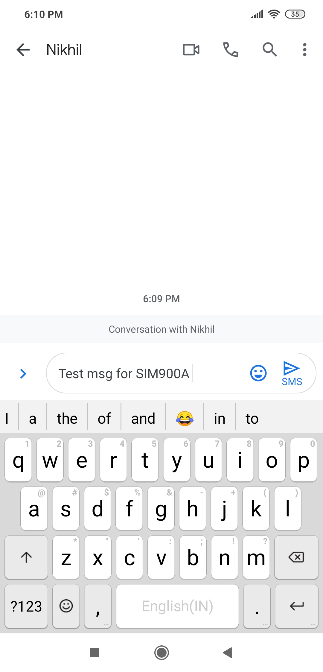
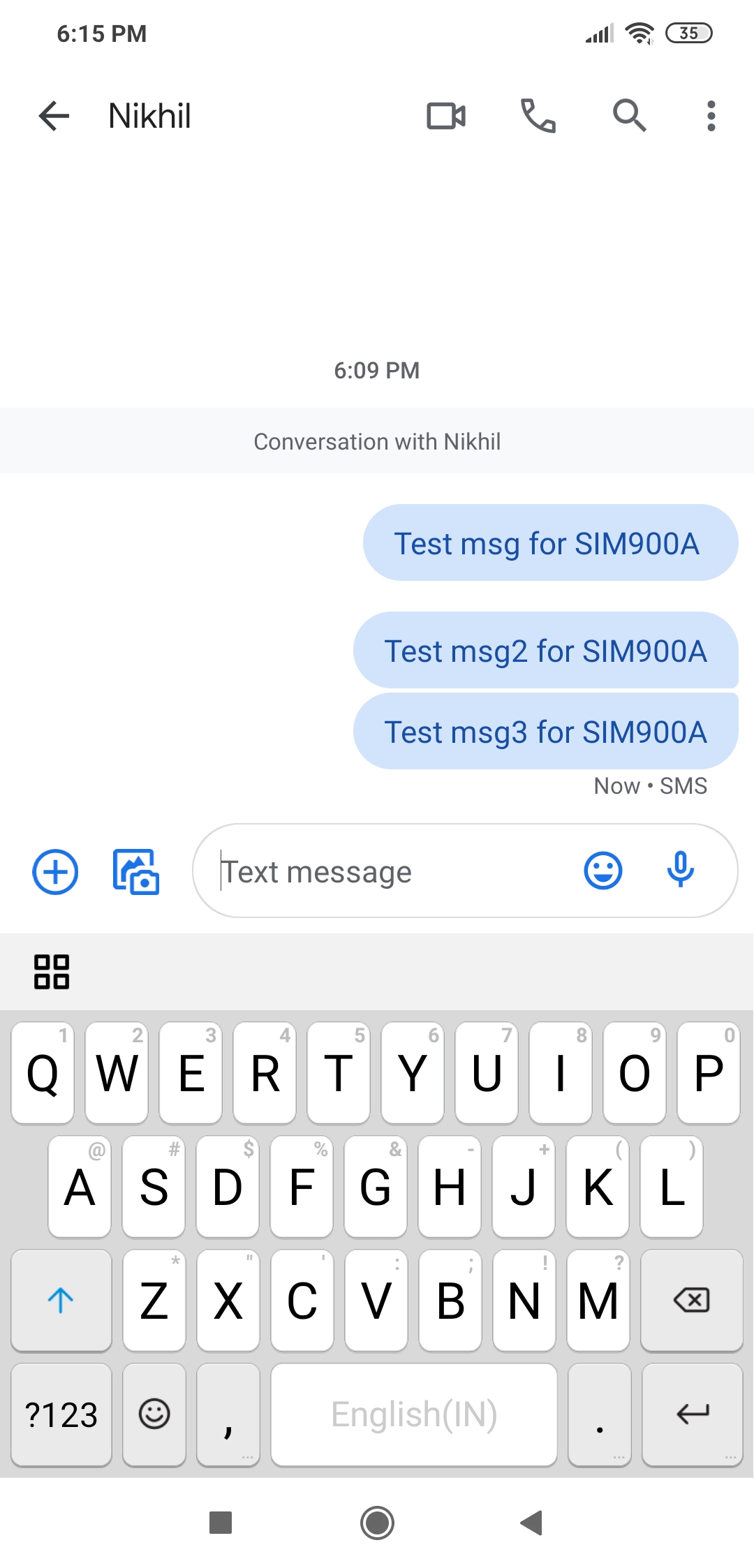
To send the SMS, first set the messaging to the text mode using “AT+CMGF=1″ command. Then, select a number to send the SMS using the AT+CMGS=”XXXXXXXXXX” command, where XXXXXXXXXX is a mobile number.
The message to be sent is stored in a variable. The output buffer is cleared using the reset_output_buffer()or the flushoutput() method but only if the serialpy version installed on RPI is less than 2.5.
The message is concatenated with CTRL+Z or a substitute character using the char(26) method. The message along with the substitute character is encoded using the str.encode() method and sent to the modem using the serial.write() method.
import serial
import os, time
import RPi.GPIO as GPIO
GPIO.setmode(GPIO.BOARD)
port = serial.Serial(“/dev/ttyS0”, baudrate=9600, timeout=1)
port.write(b’AT\r’)
rcv = port.read(10)
print(rcv)
time.sleep(1)
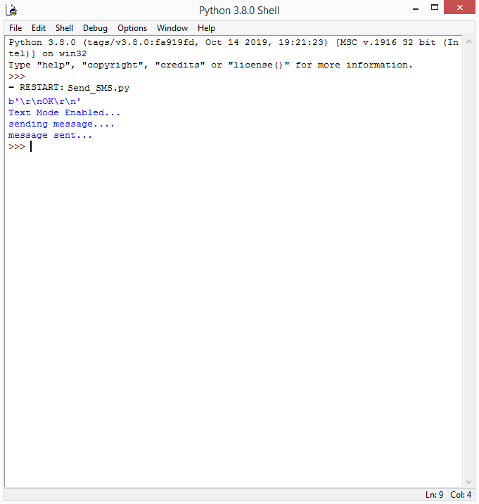
port.write(b”AT+CMGF=1\r”)
print(“Text Mode Enabled…”)
time.sleep(3)
port.write(b’AT+CMGS=”9166873301″\r’)
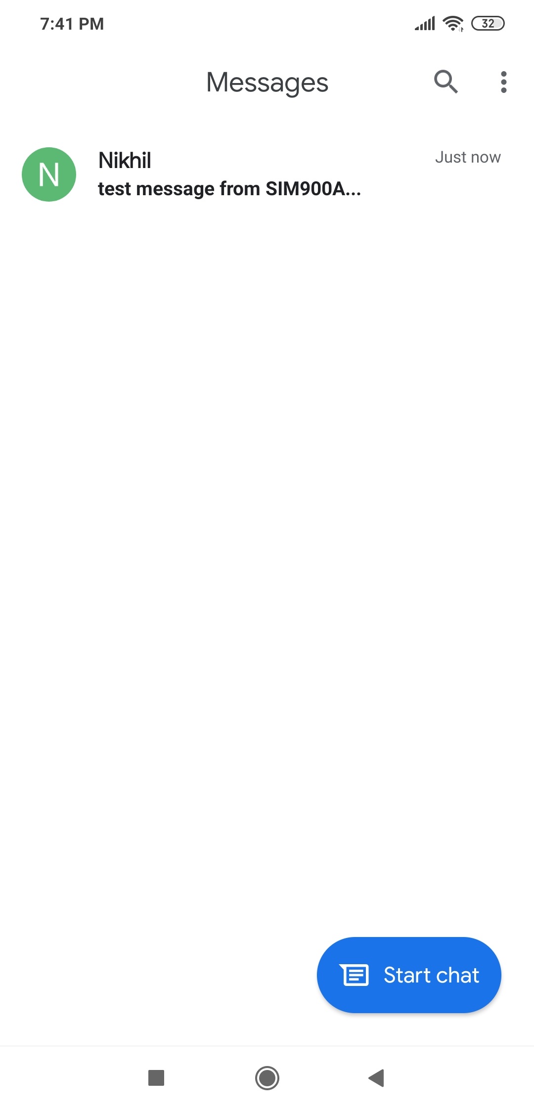
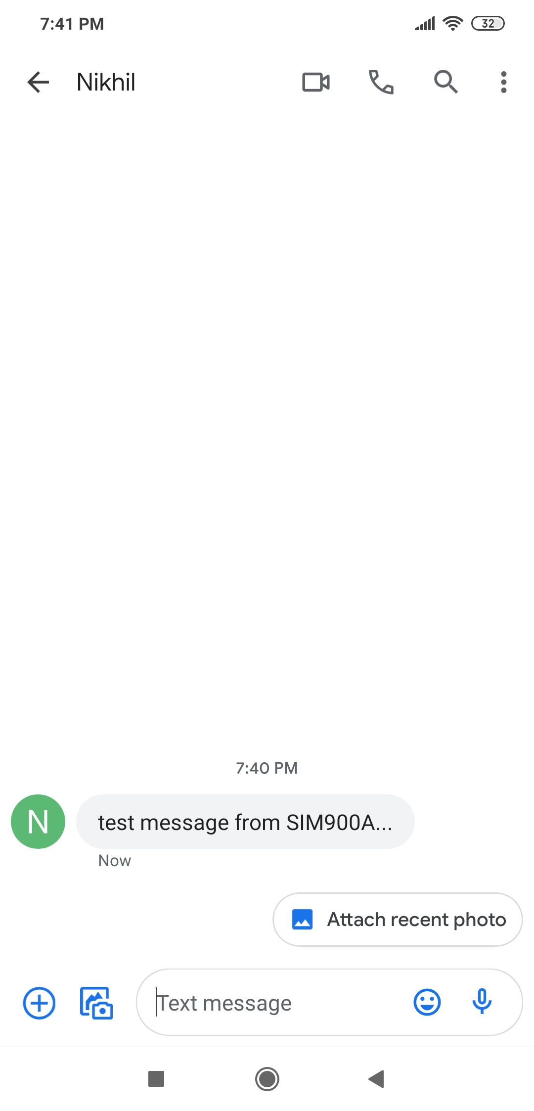
msg = “test message from SIM900A…”
print(“sending message….”)
time.sleep(3)
port.reset_output_buffer()
time.sleep(1)
port.write(str.encode(msg+chr(26)))
time.sleep(3)
print(“message sent…”)
Receiving the SMS on RPi
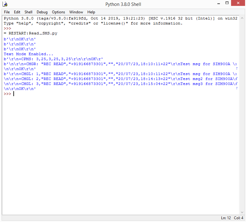
Received messages are stored in the SIM card or the phone/modem. The received SMS message at a particular index can be read by passing the AT+CMGR=<index> command. To read all of the SMS messages stored in the configured memory (either the SIM card or the phone/modem), the AT+CMGL=”ALL” command can be passed to the modem.
The modem will respond with the SMS indications and a body of the SMS that are received.
import serial
import os, time
import RPi.GPIO as GPIO
GPIO.setmode(GPIO.BOARD)
port = serial.Serial(“/dev/ttyS0”, baudrate=9600, timeout=1)
port.write(b’AT\r’)
rcv = port.read(10)
print(rcv)
time.sleep(1)
port.write(b”ATE0\r”)
rcv = port.read(10)
print(rcv)
time.sleep(1)
port.write(b”AT+CMGF=1\r”)
rcv = port.read(10)
print(rcv)
time.sleep(1)
print(“Text Mode Enabled…”)
time.sleep(1)
port.write(b’AT+CPMS=”SM”,”SM”,”SM”\r’)
rcv = port.read(30)
print(rcv)
time.sleep(1)
port.write(b’AT+CMGR=1\r’)
rcv = port.read(100)
print(rcv)
time.sleep(1)
port.write(b’AT+CMGL=”ALL”\r’)
rcv = port.read(300)
print(rcv)
time.sleep(1)
Interfacing SIM900A with a desktop computer
When using a desktop computer, the GSM-GPRS modem can be interfaced with a USB-to-serial board. The modem via USB-to-serial board is identified as a USB slave on the desktop.
After figuring out the serial port name on the desktop system (macOS, Linux, or Windows), it’s only necessary to change the serial port name in the above scripts.
The modem is interfaced to the desktop as follows:

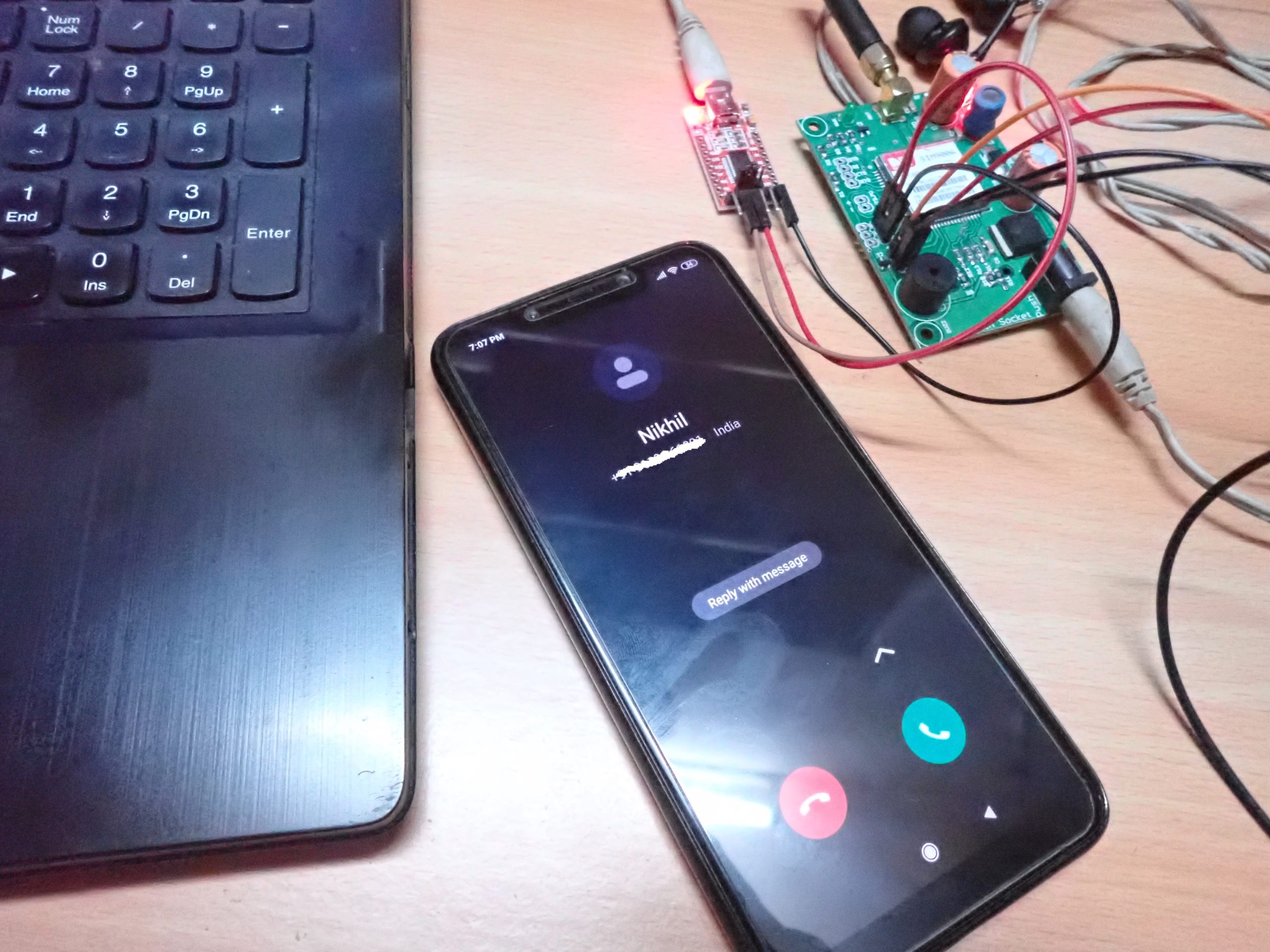
Here, we have connected the GSM-GPRS modem with a Windows computer. On our Windows desktop, the modem via the USB-serial board is identified as COM22.
Making a call from a desktop computer
As mentioned earlier in the Python script, to make a call from Raspberry Pi, first comment or remove the following RPi specific lines:
import RPi.GPIO as GPIO
GPIO.setmode(GPIO.BOARD)
port = serial.Serial(“/dev/ttyS0”, baudrate=9600, timeout=1)
Open a serial communication with the COM port, where the GSM modem is connected via the USB-serial board. Here, it is using COM22.
Add this line:
port = serial.Serial(“COM22”, baudrate=9600, timeout=1)
Now, we can make a call from the desktop using the SIM900 modem.
import serial
import os, time
#import RPi.GPIO as GPIO
#GPIO.setmode(GPIO.BOARD)
#port = serial.Serial(“/dev/ttyS0”, baudrate=9600, timeout=1)
port = serial.Serial(“COM22”, baudrate=9600, timeout=1)
port.write(b’AT\r’)
rcv = port.read(10)
print(rcv)
time.sleep(1)
port.write(b’ATD9166873301;\r’)
print(“Calling…”)
time.sleep(30)
port.write(b’ATH\r’)
print(“Hang Call…”)
The result:
Receiving a call on a desktop computer
To receive a call on a desktop computer, the process is much the same as on Raspberry Pi. We can pass the commands to end incoming call or manually answer these call using a serial application (such as Termite or Putty) on a Windows desktop.
Configuring SIM900 for SMS messaging on a desktop
Here, we also need to comment or remove RPi’s specific lines and add the proper code to open the serial COM port of a Windows desktop in the Python script – which must be written to configure the SMS settings on Raspberry Pi.
import serial
import os, time
#import RPi.GPIO as GPIO
#GPIO.setmode(GPIO.BOARD)
#port = serial.Serial(“/dev/ttyS0”, baudrate=9600, timeout=1)
port = serial.Serial(“COM22”, baudrate=9600, timeout=1)
port.write(b’AT\r’)
rcv = port.read(10)
print(rcv)
time.sleep(1)
port.write(b”ATE0\r”)
rcv = port.read(10)
print(rcv)
time.sleep(1)
port.write(b’AT+CNMI=1,1,0,0,0\r’)
rcv = port.read(30)
print(rcv)
time.sleep(1)
port.write(b’AT+CPMS=”SM”,”SM”,”SM”\r’)
rcv = port.read(30)
print(rcv)
time.sleep(1)
port.write(b’AT+CSAS\r’)
rcv = port.read(30)
print(rcv)
time.sleep(10)
port.write(b’AT+CMGDA=”DEL ALL”\r’)
rcv = port.read(30)
print(rcv)
time.sleep(1)
port.write(b’AT+CPMS=”SM”,”SM”,”SM”\r’)
rcv = port.read(30)
print(rcv)
time.sleep(1)
The result:
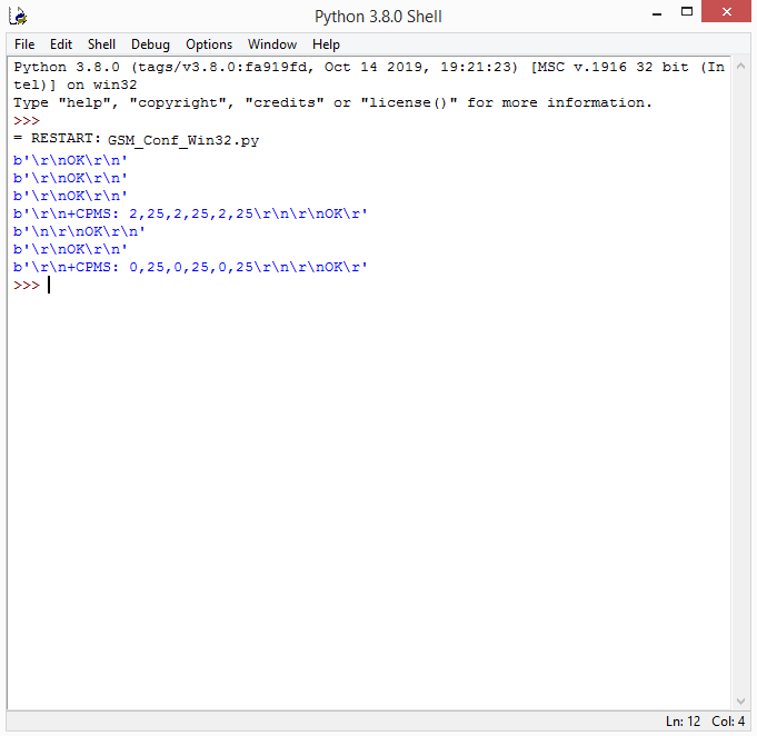
From the result codes received from the modem, a maximum of 25 messages can be stored in the SIM card. In this case, there were already two messages stored on it.
After deleting all of the current messages while in configuration, there are 0 used in the SMS memory locations.
Sending the SMS from a desktop computer
Once again, comment or remove RPi’s specific lines. Add the proper code to open the serial COM port of the Windows desktop in the Python script, which is written to send the SMS messages from Raspberry Pi.
import serial
import os, time
#import RPi.GPIO as GPIO
#GPIO.setmode(GPIO.BOARD)
#port = serial.Serial(“/dev/ttyS0”, baudrate=9600, timeout=1)
port = serial.Serial(“COM22”, baudrate=9600, timeout=1)
port.write(b’AT\r’)
rcv = port.read(10)
print(rcv)
time.sleep(1)
port.write(b”AT+CMGF=1\r”)
print(“Text Mode Enabled…”)
time.sleep(3)
port.write(b’AT+CMGS=”9166873301″\r’)
msg = “test message from SIM900A…”
print(“sending message….”)
time.sleep(3)
port.reset_output_buffer()
time.sleep(1)
port.write(str.encode(msg+chr(26)))
time.sleep(3)
print(“message sent…”)
The result:
Receiving the SMS on a desktop computer
It’s also necessary to comment or remove RPi’s specific lines here. Add code to open the serial COM port of the Windows desktop in the Python script, which is written to receive the SMS on Raspberry Pi.
import serial
import os, time
#import RPi.GPIO as GPIO
#GPIO.setmode(GPIO.BOARD)
#port = serial.Serial(“/dev/ttyS0”, baudrate=9600, timeout=1)
port = serial.Serial(“COM22”, baudrate=9600, timeout=1)
port.write(b’AT\r’)
rcv = port.read(10)
print(rcv)
time.sleep(1)
port.write(b”ATE0\r”)
rcv = port.read(10)
print(rcv)
time.sleep(1)
port.write(b”AT+CMGF=1\r”)
rcv = port.read(10)
print(rcv)
time.sleep(1)
print(“Text Mode Enabled…”)
time.sleep(1)
port.write(b’AT+CPMS=”SM”,”SM”,”SM”\r’)
rcv = port.read(30)
print(rcv)
time.sleep(1)
port.write(b’AT+CMGR=1\r’)
rcv = port.read(100)
print(rcv)
time.sleep(1)
port.write(b’AT+CMGL=”ALL”\r’)
rcv = port.read(300)
print(rcv)
time.sleep(1)
The result:
Note: the received SMS messages are stored in the SIM card, so we are passing commands to read those messages from the SIM card’s memory locations.
Now you can interface a SIM900 GSM-GPRS modem with Raspberry Pi and any desktop system. This includes making and receiving calls and sending and receiving SMS messages.
In the next tutorial, we’ll learn how to interface a GPS modem with Raspberry Pi and a desktop computer.
Filed Under: Raspberry pi

Questions related to this article?
👉Ask and discuss on EDAboard.com and Electro-Tech-Online.com forums.
Tell Us What You Think!!
You must be logged in to post a comment.