The Mouse and keyboard are most common computer peripherals. While the mouse is a pointing device and helps in tapping the GUI elements of the screen, the keyboard has greater role to play with handling data input as well as has the ability to navigate through GUI elements of a screen. Nowadays the keyboards interface with the computers through USB cable and use USB protocol to send data inputs to the computers. The wireless type keyboards generally use Bluetooth to send data inputs to the computers. In fact, wireless keyboards also use an external pluggable device which ultimately connects to the PC by USB Port. This project is to demonstrate the basic functioning and working of a generic USB keyboard. The 8-bit USB AVR – Atmega 32u4 is used as the device controller chip in the project. The project uses AVR based Lightweight USB Framework (LUFA) as the firmware which is modified to work for this custom keyboard.

Fig.1: Prototype of Arduino based DIY USB Keyboard
Usually, the Windows keyboard has 104 keys which is the de facto standard and the windows based laptops have 86-key keyboards. An Apple keyboard has 109 keys as the standard and Apple laptops have 78-key keyboard. In this project, a 4-key keyboard is built to demonstrate the making of keyboards. The LUFA firmware is used and its HID device driver class for keyboard is modified to program the project. With the use of LUFA firmware, the device driver code to implement USB protocol is not needed to be written explicitly. Modifying the firmware code to work for the project will be sufficient. The project works similar to any generic USB keyboard and has buttons for the following Inputs -:
• Input H Alphabet to the computer
• Input I Alphabet to the computer
• Turn Caps lock ON or OFF
• Left Shift Key
The project uses tactile switches as the buttons, Atmega 32u4 as the controller chip (on board Arduino Pro Micro) and USB cable to connect to the personal computer.
PREREQUISITES
This project is based on Arduino Pro Micro which has the USB AVR – Atmega 32u4 as the sitting MCU. In order to understand this project, one must have basic knowledge of the AVR microcontrollers and the embedded C programming for AVRs. WinAVR Studio is used to write, edit and compile the project code, so closely following the project shall require familiarizing with the above stated IDE as well. Though LUFA framework takes care of implementing the USB protocol and has APIs to abstract the lower level codes, understanding USB protocol is recommended to understand how actually the project is working. In fact, if anyone has already worked on some other microcontroller, it will not be much pain to understand and follow this project as the project code is more or less about getting input from the GPIO pins of AVR MCU and modifying the LUFA device driver to work as generic keyboard accordingly.

Fig. 2: Image showing alphabet ‘h’ typed from Arduino based generic USB keyboard
COMPONENTS REQUIRED
1. Arduino Pro Micro
2. Breadboard
3. Connecting wires
4. Push buttons
5. Micro USB cable
6. 10K resistors
7. 220 Ω resistor
SOFTWARE TOOLS REQUIRED
1. WinAVR Studio
2. AVR Dude
3. LUFA Firmware
BLOCK DIAGRAM

Fig. 3: Block Diagram of Arduino based DIY USB Keyboard
CIRCUIT CONNECTIONS
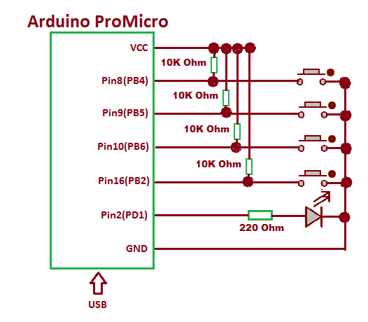
The project uses Arduino Pro Micro as the USB controller chip. A set of four tactile switches is connected at the port B of the Arduino. The switches are connected to pins 2, 6, 5 and 4 of the port B with functions assigned to them according to the following table -:

Fig. 4: Table listing Arduino pins and respective keyboard functions
An LED is connected at the pin 1 of Port D via 220 Ω pull up resistor to get the visual hint of the status of Caps Lock Key. The tactile switches are connected between the port and ground. The pins of port B by default are connected to VCC and receive a HIGH logic.
Pressing a tactile switch changes the status at the respective pin to LOW by short circuiting to the ground.
The Program code for the project is burnt to the Arduino Pro Micro using AVR Dude. The Arduino board is connected to the USB port of a PC by a USB cable.
HOW THE PROJECT WORKS
In this project, the USB protocol is implemented by the LUFA framework. For configuring the controller chip to work as USB Keyboard, the HID Class Driver of the LUFA framework will be used. The Human Interface Device (HID) class takes care of the transfers between the host device and the human controlled USB peripherals like USB Keyboard, Mouse or Joystick.
When a USB device is attached to the host (PC), the host sends request for configuration details in the form of the control transfer. The connected device has to respond with appropriate descriptors to get configured and ready for further operations. Only after configuration, the device can communicate with the host in the form of interrupt, isochronous or bulk transfers for executing the operations for which the device has been made. In case of keyboard, after configuring with the host device, it has to communicate with the host in the form of interrupt transfers for the intended keyboard like operations. The process of identification and configuration of the device with the host is called enumeration.
A typical keyboard has many types of keys like -:
• Modifier Keys: They are Right Ctrl and Left Ctrl, Right Alt and Left Alt, Right Shift and Left Shift, Right GUI, and Left GUI.
• Alphanumeric Keys: A – Z and 0 – 9
• Numeric Keys – keys present on Numeric Keypad
• Punctuation Keys – For example, comma, semicolon, bracket key etc.
• System Keys – For example, escape, break key
• Function Keys – Keys present on top of the keyboard like F1, F2 etc.
• Special Keys – For example, delete, arrow keys etc
According to the USB protocol, keys pressed on a keyboard are identified by the key codes. This is same as the ASCII codes are used to represent characters. Like keycode representing spacebar is 41 so when spacebar is pressed, the controller chip sends the binary representation of 41 (0x29) to the host in appropriate data format to the host to indicate that spacebar has been pressed. The standard keycodes for different keys are given in the HID Usage Table provided by the USB Implementers Forum.
As mentioned earlier, a windows keyboard has 104 keys while the number of characters that can be input through a keyboard is more than that. A lot of characters are input by pressing shift key along with another key which already represents another character. Like to input exclamation “!” character, shift key along with the key “1” has to be pressed. When key “1” is pressed weather along shift or not, the same keycode is transferred. However when it will be pressed along with the shift key, set of two keycodes, one for shift key and other for “1” key will be transferred which will then be interpreted as an exclamation “!” character. The same happens for the lower case and upper case alphabets too.
A keyboard is HID class USB device and LUFA framework has HID class related module in the LUFA-Source-Folder /LUFA/Drivers/USB/Class/Device folder. Other device class related module are also in the same folder. The LUFA framework has demo projects for different USB device classes in the LUFA-Source-FolderDemosDeviceClassDriver folder. For implementing the project, demo project for keyboard provided in the LUFA framework will be modified and complied. The demo project for keyboard is in the LUFA-Source-FolderDemosDeviceClassDriverKeyboard folder. The folder contains keyboard.c file which will be modified to work for our custom keyboard device.

Fig. 5: Image showing capital ‘i’ typed from Arduino based generic USB keyboard
How Keyboard.c identifies HID device being Keyboard
The keyboard.c uses Keyboard_HID_Interface interface in HID_Device_USBTask() function which is being imported from the HIDDeviceClass.c (from LUFA-Source-Folder LUFADriversUSBClassDevice) to configure the device as keyboard. The interface abstracts the low-level descriptor codes and identifies the device as keyboard through an InterfaceNumber variable.
Keyboard Specific Report DescriptorsAny HID device has to exchange data with the host which should be structured in the form of reports. The report descriptor defines the report structure. A report descriptor contains the information needed by host to determine the data format and how the data should be processed by the host. Therefore, a report descriptor basically structures the data that needs to be exchanged with the host according to the USB protocol.
For working like a keyboard, the device needs to send usage report and data input report descriptors specific to keyboard HID Class to the host while it itself needs to interpret data output report specific to keyboard HID Class received from the host device. The Usage Report informs the Host about the features or functionality of the USB device whereas the Data Input Report is used to transmit the data to the Host. The Data Output Report is used to receive data from the host.
From Where Keyboard.C gets the USAGE and Data Reports Descriptors
In the LUFA framework’s demo project for Keyboard, descriptor.c file is imported in keyboard.c to send the relevant usage and data reports descriptors to the host device. The descriptor.c defines a KeyboardReport[] structure which is used in the CALLBACK_HID_Device_CreateHIDReport() function of the keyboard.c to generate keyboard specific usage and data reports descriptors. Inside descriptor.c the KeyboardReport[] structure has the values returned by HID_DESCRIPTOR_KEYBOARD () function. The HID_DESCRIPTOR_KEYBOARD() is defined in HIDClassCommon.h (located in LUFA-Source-FolderLUFADriversUSBClassCommon folder). The keyboard.c imports keyboard.h which imports usb.h. USB.h imports HIDCLass.h. In HIDClass.h is imported HIDClassDevice.h if the USB_CAN_BE_DEVICE is true for the controller chip to being a USB device, not the host. The HIDClassDevice.h imports HIDClassCommon.h where the HID device specific descriptor fields have been defined.
USAGE REPORT
HID_DESCRIPTOR_KEYBOARD () returns the following field values of the usage report descriptor, specific to keyboard functioning -:

Fig. 6: Table listing field values of the usage report descriptor from HID_DESCRIPTOR_KEYBOARD Function
These fields are set to following values in HID_DESCRIPTOR_ KEYBOARD()

Fig. 7: Screenshot of field values of the usage report descriptor from HID_DESCRIPTOR_KEYBOARD Function
The Usage or Feature report contains information about the features of the device. In other words, this report informs Host about the features needed in the device. For example, a Keyboard device generally contains feature information like a number of modifier keys, the number of other keys and number of LEDs used for status indication. The Host can access this report by requesting the device using GET_REPORT request. This report is transmitted using Control Transfer Type of the USB protocol.
DATA INPUT REPORT
The Data Input Report contains the data that needs to be transmitted to the Host. It contains data related to the features selected via the Usage Report. Again in the HIDClassCommon.h a structure for data report of keyboard is defined in the following manner.

Fig: 8: Screenshot of Data Input Report from HIDClassCommon.h in LUFA Library
The data input report for keyboard consist of 8 bytes of which 6 bytes are used to represent keycodes of maximum six keys pressed together, one byte is reserved for OEM and is always set to 0 and one byte is for the modifier key. The field values specific to data report for keyboard are organised in the following manner -:

Fig. 9: Table listing field values specific to data report for this keyboard
DATA OUTPUT REPORT
The Data Output report contains the information related to the status of LEDs present on a keyboard. These LEDs indicate the active status of CAPSLOCK key, SCROLL key and NUMLOCK key. Through this report, the Host informs the device to switch ON/OFF the LEDs as per respective key activity. For example, when the CapsLock is pressed, the Host will inform the device to switch ON the LED for CapsLock Key. This report is 1-byte long with first 3 LSBs indicating the status of each LED. The other bits are not used. If the respective bit is set to 0, it indicates the respective key is OFF and if respective bit is set to 1, it indicates the respective key is ON.

Fig. 10: Screenshot of Data Output Report from HIDClassCommon.h in LUFA Library
HOW THE DEVICE WORKS
The AVR microcontroller is programmed to work with the tactile switches as keyboard buttons. The main() function, the CALLBACK_HID_Device_CreateHIDReport() function and CALLBACK_HID_Device_ProcessHIDReport() function of the keyboard.c are modified to customize the device for working with tactile switches as source for reading desired keycodes. Check out the program code to see the modifications implemented for this custom keyboard.
PROGRAMMING GUIDE
For building the project download the LUFA framework from the github.com. The demo project provided with the LUFA framework is modified to make this custom keyboard. In the extracted LUFA zip file, open Demos/Device/ClassDriver/Keyboard folder. The folder has the following files and folders.

Fig. 11: Screenshot of Data Output Report from HIDClassCommon.h in LUFA Library
Of these, Keyboard.h, Keyboard.c, and Makefile needs to be modified for this project. The modified files (provided at the bottom of the article in zip format) can also be downloaded from the engineersgarage and replaced with the original files. Either open the files in WinAVR Studio or Notepad++ and modify original files or replace files with the already modified one. The modified or replaced Keyboard.c needs to be compiled from within the LUFA’s Source folder to get the object code.
Modifying Keyboard.h
The Keyboard.h library file is imported in the Keyboard.c file and includes a set of additional libraries and defines the constants and functions for the keyboard device. These include the additional libraries for the joystick, button, and LEDs which should be commented out as the project is not using these HID features. So open Keyboard.h and make the following changes -:
• Comment the #include library statements for Joystick.h, LEDS.h, and Buttons.h ( We are commenting these libraries as we are not using any joystick, buttons board and LED board).
• Comment the #define statements for LEDMASK_USB_NOTREADY, LEDMASK_USB_ENUMERATING, LEDMASK_USB_READY, LEDMASK_USB_ERROR.
Save the file with changes.
Modifying Keyboard.C file
Again in the Keyboard.c, the code sections for Joystick, button board and LEDs need to be commented out. So open Keyboard.c and make the following changes – :
• In the main loop, comment the LEDs_SetAllLEDs()
• In SetupHardware() function, comment the Joystick_Init(), LEDs_Init(), Buttons_Init()
• In EVENT_USB_Device_Connect() function, comment the LEDs_SetAllLEDs()
• In EVENT_USB_Device_Disconnect() function, comment LEDs_SetAllLEDs()
• In EVENT_USB_Device_ConfigurationChanged() function, comment the LEDs_SetAllLEDs()
In Keyboard.c the main() function executes the functioning of the Keyboard. Inside the main function Port B where the tactile switches have been connected needs to be defined as input and all the pins of port B has to be raised to HIGH logic by default as the microcontroller will need to detect LOW logic for input from tactile switches. Similarly Port D where Capslock LED is connected has to be made output port and has to be raised to LOW logic by default, so add the following statements in the beginning of main() function -:
Inside the infinite, for loop, the HID_Device_USBTask() function is called where Keyboard_HID_Interface interface is passed as parameter. The interface identifies the device as keyboard and abstracts the low-level program code specific to keyboard HID class. The function is coming from the HIDClassDevice.c module (located in LUFA/Drivers/USB/Class/Device/HIDClassDevice.c) and is used for general management task for a given HID class interface, required for the correct operation of the interface. It should be called in the main program loop, before the master USB management task USB_USBTask(). The USB_USBTask() is the main USB management task. The USB driver requires this task to be executed continuously when the USB system is active (device attached in host mode, or attached to a host in device mode) in order to manage USB communications. The function is defined in USBTask.c (Located in LUFA-Source-FolderLUFADriversUSBCore folder).
For creating Keyboard Data Input report CALLBACK_HID_Device_CreateHIDReport() needs to be modified. The default file has the function body to detect joystick movement as well.

Fig. 12: Screenshot of LUFA Library Folder on Windows
This keyboard project is using tactile switches to get keycodes. Therefore, LOW bit at each button is detected and the corresponding keycode is sent via data input report for the keyboard. So replace the body of the function with the following code -:
In the body BV() function is used to map the respective bit as a byte with only the respective bit changed in the returned byte.
The Data Output Report is handled by the CALLBACK_HID_Device_ProcessHIDReport() function. In the unedited LUFA file, this function has statements to turn the LEDs associated with modifier keys ON or OFF and has the following body -:

Fig. 13: Screenshot of CALLBACK_HID_Device_CreateHIDReport Function in LUFA Library
First, remove the statements that are not required. These statements are as follow -:
• uint8_t LEDMask = LEDS_NO_LEDS;
• All if conditions and their statements
• LEDs_SetAllLEDs(LEDMask)
Now add the statements given below to the function body -:
void
These statements check the status of CapsLock key as received from the host device and accordingly turns the LED connected at pin 1 of port D ON or OFF accordingly.
Save the file and create Make file for the project.
Modifying Make File
In the Keyboard folder, there is a make file that needs to be edited. The file can be edited using Notepad++. The following information needs to be edited -:
• MCU = atmega32u4
• ARCH = AVR8
• BOARD = LEONARDO
• F_CPU = 16000000
Save the file and exit. Now all the files are edited completely for the basic HID Keyboard application.
Compiling Keyboard.c
For compiling the source code, WinAVR Programmers Notepad or Arduino IDE can be used. Open the modified Keyboard.c file and compile the code.
Burning Hex code
The hex file is generated on compiling the keyboard.c file. For burning the object code to microcontroller open the Command Prompt, change the current directory to the directory containing the Hex file. This can be done using command: CD <address of the directory>. Now reset the Arduino and instantly run the command: : avrdude -v -p atmega32u4 -c avr109 -P COM20 -b 57600 -D -Uflash:w:Keyboard.hex:i after replacing the COM Port with the recognized one.
If the uploading process is successful, the Arduino will be shown as HID Keyboard in the Device Manager. There is no need of installing any driver in the computer as Generic HID Keyboard is used for the project implementation. Use the buttons to test the project device working as generic USB Keyboard.
In the next project – Custom Browser Keypad, learn how to make a keyboard to work specially with the desktop browser.
Project Source Code
###
/* LUFA Library Copyright (C) Dean Camera, 2015. dean [at] fourwalledcubicle [dot] com www.lufa-lib.org */ /* Copyright 2015 Dean Camera (dean [at] fourwalledcubicle [dot] com) Permission to use, copy, modify, distribute, and sell this software and its documentation for any purpose is hereby granted without fee, provided that the above copyright notice appear in all copies and that both that the copyright notice and this permission notice and warranty disclaimer appear in supporting documentation, and that the name of the author not be used in advertising or publicity pertaining to distribution of the software without specific, written prior permission. The author disclaims all warranties with regard to this software, including all implied warranties of merchantability and fitness. In no event shall the author be liable for any special, indirect or consequential damages or any damages whatsoever resulting from loss of use, data or profits, whether in an action of contract, negligence or other tortious action, arising out of or in connection with the use or performance of this software. */ /** file * * Main source file for the Keyboard demo. This file contains the main tasks of * the demo and is responsible for the initial application hardware configuration. */ #include "Keyboard.h" /** Buffer to hold the previously generated Keyboard HID report, for comparison purposes inside the HID class driver. */ static uint8_t PrevKeyboardHIDReportBuffer[sizeof(USB_KeyboardReport_Data_t)]; /** LUFA HID Class driver interface configuration and state information. This structure is * passed to all HID Class driver functions, so that multiple instances of the same class * within a device can be differentiated from one another. */ USB_ClassInfo_HID_Device_t Keyboard_HID_Interface = { .Config = { .InterfaceNumber = INTERFACE_ID_Keyboard, .ReportINEndpoint = { .Address = KEYBOARD_EPADDR, .Size = KEYBOARD_EPSIZE, .Banks = 1, }, .PrevReportINBuffer = PrevKeyboardHIDReportBuffer, .PrevReportINBufferSize = sizeof(PrevKeyboardHIDReportBuffer), }, }; /** Main program entry point. This routine contains the overall program flow, including initial * setup of all components and the main program loop. */ int main(void) { SetupHardware(); DDRD = 0XFF; DDRB = 0X00; PORTB = 0XFF; PORTD = 0X00; //LEDs_SetAllLEDs(LEDMASK_USB_NOTREADY); GlobalInterruptEnable(); for (;;) { HID_Device_USBTask(&Keyboard_HID_Interface); USB_USBTask(); } } /** Configures the board hardware and chip peripherals for the demo's functionality. */ void SetupHardware() { #if (ARCH == ARCH_AVR8) /* Disable watchdog if enabled by bootloader/fuses */ MCUSR &= ~(1 << WDRF); wdt_disable(); /* Disable clock division */ clock_prescale_set(clock_div_1); #elif (ARCH == ARCH_XMEGA) /* Start the PLL to multiply the 2MHz RC oscillator to 32MHz and switch the CPU core to run from it */ XMEGACLK_StartPLL(CLOCK_SRC_INT_RC2MHZ, 2000000, F_CPU); XMEGACLK_SetCPUClockSource(CLOCK_SRC_PLL); /* Start the 32MHz internal RC oscillator and start the DFLL to increase it to 48MHz using the USB SOF as a reference */ XMEGACLK_StartInternalOscillator(CLOCK_SRC_INT_RC32MHZ); XMEGACLK_StartDFLL(CLOCK_SRC_INT_RC32MHZ, DFLL_REF_INT_USBSOF, F_USB); PMIC.CTRL = PMIC_LOLVLEN_bm | PMIC_MEDLVLEN_bm | PMIC_HILVLEN_bm; #endif /* Hardware Initialization */ //Joystick_Init(); //LEDs_Init(); //Buttons_Init(); USB_Init(); } /** Event handler for the library USB Connection event. */ void EVENT_USB_Device_Connect(void) { //LEDs_SetAllLEDs(LEDMASK_USB_ENUMERATING); } /** Event handler for the library USB Disconnection event. */ void EVENT_USB_Device_Disconnect(void) { //LEDs_SetAllLEDs(LEDMASK_USB_NOTREADY); } /** Event handler for the library USB Configuration Changed event. */ void EVENT_USB_Device_ConfigurationChanged(void) { bool ConfigSuccess = true; ConfigSuccess &= HID_Device_ConfigureEndpoints(&Keyboard_HID_Interface); USB_Device_EnableSOFEvents(); //LEDs_SetAllLEDs(ConfigSuccess ? LEDMASK_USB_READY : LEDMASK_USB_ERROR); } /** Event handler for the library USB Control Request reception event. */ void EVENT_USB_Device_ControlRequest(void) { HID_Device_ProcessControlRequest(&Keyboard_HID_Interface); } /** Event handler for the USB device Start Of Frame event. */ void EVENT_USB_Device_StartOfFrame(void) { HID_Device_MillisecondElapsed(&Keyboard_HID_Interface); } /** HID class driver callback function for the creation of HID reports to the host. * * param[in] HIDInterfaceInfo Pointer to the HID class interface configuration structure being referenced * param[in,out] ReportID Report ID requested by the host if non-zero, otherwise callback should set to the generated report ID * param[in] ReportType Type of the report to create, either HID_REPORT_ITEM_In or HID_REPORT_ITEM_Feature * param[out] ReportData Pointer to a buffer where the created report should be stored * param[out] ReportSize Number of bytes written in the report (or zero if no report is to be sent) * * return Boolean c true to force the sending of the report, c false to let the library determine if it needs to be sent */ bool CALLBACK_HID_Device_CreateHIDReport(USB_ClassInfo_HID_Device_t* const HIDInterfaceInfo, uint8_t* const ReportID, const uint8_t ReportType, void* ReportData, uint16_t* const ReportSize) { USB_KeyboardReport_Data_t* KeyboardReport = (USB_KeyboardReport_Data_t*)ReportData; uint8_t UsedKeyCodes = 0; if(!(PINB & _BV(PB4))) { // add keycode for ‘h’ alphabet in the report KeyboardReport->KeyCode[UsedKeyCodes++] = HID_KEYBOARD_SC_H; } if(!(PINB& _BV(PB5))) { // add keycode for ‘i’ alphabet in the report KeyboardReport->KeyCode[UsedKeyCodes++] = HID_KEYBOARD_SC_I; } if(!(PINB & _BV(PB6))) { // add keycode for Caps Lock in the report KeyboardReport->KeyCode[UsedKeyCodes++] = HID_KEYBOARD_SC_CAPS_LOCK; } if(!(PINB & _BV(PB2))) { // add keycode for modifier shift key in the report KeyboardReport->Modifier = HID_KEYBOARD_MODIFIER_LEFTSHIFT; } *ReportSize = sizeof(USB_KeyboardReport_Data_t); return false; } /** HID class driver callback function for the processing of HID reports from the host. * * param[in] HIDInterfaceInfo Pointer to the HID class interface configuration structure being referenced * param[in] ReportID Report ID of the received report from the host * param[in] ReportType The type of report that the host has sent, either HID_REPORT_ITEM_Out or HID_REPORT_ITEM_Feature * param[in] ReportData Pointer to a buffer where the received report has been stored * param[in] ReportSize Size in bytes of the received HID report */ void CALLBACK_HID_Device_ProcessHIDReport(USB_ClassInfo_HID_Device_t* const HIDInterfaceInfo, const uint8_t ReportID, const uint8_t ReportType, const void* ReportData, const uint16_t ReportSize) { uint8_t* LEDReport = (uint8_t*)ReportData; if (*LEDReport & HID_KEYBOARD_LED_CAPSLOCK) { // switch on the LED for Caps Lock PORTD |= 0x02; // make PD1 high } else { // switch off the LED PORTD &= 0xfd; // make PD1 low } }/restrict]
Circuit Diagrams
Project Datasheet
Project Video
Filed Under: Electronic Projects
Filed Under: Electronic Projects

Questions related to this article?
👉Ask and discuss on EDAboard.com and Electro-Tech-Online.com forums.
Tell Us What You Think!!
You must be logged in to post a comment.