External memories are frequently used to store and carry computer data. The USB flash drives are quite common nowadays. This project is an attempt to demonstrate making of USB storage devices. The project converts an external EEPROM which basically has I2C interface to an USB device. The project actually works like a protocol changer between I2C and USB standards. The external EEPROM used in the project is AT24C512 which has 512 Kb memory space. In this project a desktop application written in Python will be used to write, read and erase data from the EEPROM. The 8-bit USB AVR – Atmega 32u4 will be used as the controller chip on the device to accept control instructions from the host computer according to USB protocol and implement the data control operations on EEPROM through I2C protocol. The project device uses AVR based Lightweight USB Framework (LUFA) as the firmware to implement the USB protocol as well as perform the protocol conversion.
The LUFA’s communication device class (CDC) is modified to program the project. By using the LUFA firmware, the device driver code to implement USB protocol and the I2C protocol will not needed to be written explicitly. By only using an API provided in the open source framework, the conversion between the protocols will be done.
The Communication Device Class (CDC) devices can basically perform three tasks -:
• Device management (configuration of specific devices, notification of certain events)
• Call management (Establishment of telephone calls or termination)
• Data transmission (sending and receiving device data)
This project uses CDC class driver for the data transmission purpose.

Fig. 1: Prototype of Arduino based USB EEPROM Reader
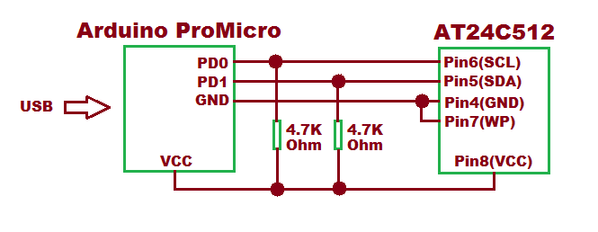
The project is built on Arduino Pro Micro. The device does to need any human inputs. The Control instructions from host computer on USB are received by the device from the USB port of the Arduino board. For interfacing with the EEPROM through I2C, SDA (PD1) and SCL (PD0) pins of the Arduino Pro Micro are connected with the SDA and SCL pins of the EEPROM chip.
PREREQUISITES
This project is based on Arduino Pro Micro which has the USB AVR – Atmega 32u4 as the sitting MCU. In order to understand this project, one must have basic knowledge of the AVR microcontrollers and the embedded C programming for AVRs. WinAVR Studio is used to write, edit and compile the project code, so closely following the project shall require familiarizing with the above stated IDE as well. Though LUFA framework takes care of implementing the USB protocol as well as I2C protocol and has APIs to abstract the lower level codes, understanding USB protocol is recommended to understand how actually the project works. In fact, if anyone has already worked on some other microcontroller, it will not be much pain to understand and follow the project. The project is based on using APIs of the LUFA framework and modifying the demo files that comes with the framework itself.
COMPONENTS REQUIRED
1. Arduino Pro Micro
2. Connecting wires
3. Micro USB cable
4. I2C EEPROM (AT24C512)
5. 4.7K Ohms resistors – 2
SOFTWARE TOOLS REQUIRED
1. WinAVR Studio
2. AVR Dude
5. Pyserial 2.7
BLOCK DIAGRAM

Fig. 2: Block Diagram of Arduino based USB EEPROM Reader
CIRCUIT CONNECTIONS
The project is built on Arduino Pro Micro in which Atmega 32u4 works as the controller chip. The USB to I2C protocol conversion is carried out on the Arduino board itself. The Arduino board has in-built USB port to connect with the personal computer and has SDA (PD1) and SCL (PD0) pins for serial communication on I2C. So only the Arduino board is needed and connecting wires for connecting with EEPROM through I2C interface and USB cable for connecting with the PC are required. The Arduino board and EEPROM are connected according to the following table -:

Fig. 3: Table listing circuit connections between Arduino Pro Micro and AT24C512 EEPROM
As per the I2C standard, 4.7 KΩ resisters are used to pull up SDA and SCL pins. The Program code for the project is burnt to the Arduino Pro Micro using AVR Dude. Once the firmware is loaded to the Arduino board, the device works like an USB flash drive having 512 Kb memory.
HOW THE PROJECT WORKS
In this project USB protocol needs to be implemented and an API of virtual serial device from the LUFA framework is used to implement the project. The device is configured to communication device class (CDC). For protocol conversion, the device is configured to Abstract Control Model Subclass. The USB communications device class (CDC) is a composite USB device class, and the class may include more than one interface.
The project is USB CDC class device. In the LUFA framework CDC class related modules are in the LUFA-Source-Folder /LUFA/Drivers/USB/Class/Device folder. Other device class related module are also in the same folder. The LUFA framework has demo projects for different USB device classes in the LUFA-Source-FolderDemosDeviceClassDriver folder. For implementing the project, demo project for virtual serial device provided in the LUFA framework will be modified and complied. The demo project for virtual serial device is in the LUFA-Source-FolderDemosDeviceClassDriverVirtualSerial folder. The folder contains VirtualSerial.c file which will be modified to implement the project. An additional file will be imported for implementing the I2C protocol which will be written explicitly.

Fig. 4: Image of Arduino based USB EEPROM Reader
How VirtualSerial.c identifies device a CDC USB Device
The VirtualSerial.c uses VirtualSerial_CDC_Interface interface in CDC_Device_USBTask () function which is being imported from the CDCDeviceClass.c (from LUFA-Source-Folder LUFADriversUSBClassDevice) to configure the device as USB CDC device. The interface abstracts the low-level descriptor codes and identifies the device as CDC device through an InterfaceNumber variable.
USB CDC Specific Descriptors
Like any USB device configure and exchange data with the host by sending descriptors in response to requests from the host device, the USB CDC devices also connect with a host via request-descriptor mechanism. At application layer descriptors are structured in the form of reports. Every report descriptor has a report structure. A report descriptor contains the information needed by host to determine the data format and how the data should be processed by the host. Therefore, a report descriptor basically structure the data that needs to be exchanged with the host according to the USB protocol.
When an USB CDC device is connected to the host computer, the host sends request for configuration in the form of control transfer. This is common for all USB peripherals or devices. Any CDC device for configuring with a host has to respond with Class Request, Class Notification and Endpoint Configuration. These information are passed through the Usage report to the host as the Usage Report informs the Host about the features or functionality of the USB device.
The usage and data report associated with CDC USB devices are defined in the CDCClassCommon.h file in the LUFA framework. The file is located in the LUFA-Source-Folder/LUFA/Drivers/USB/Class/Common folder. The CDC class allows an USB device to connect with various other interfaces and protocols like for the ISDN, fax, Ethernet, telephone etc. In the usage report, a CDC device has to acknowledge its class, subclass and protocol values. Learn more about the CDC class related requests, descriptors and enumeration process from Atmega 32u4 Based UART to USB Converter Project. Once the device is configured with the host, it uses bulk transfers to write, read or erase data from the EEPROM.
From Where VirtualSerial.C gets the USAGE and Data Report Descriptors
In the LUFA framework’s demo project for Virtual Serial, VirtualSerial.c file imports VirtualSerial.h where the descriptors.h is imported. The descriptor.h has the structures defining CDC class related descriptors which have been explained in the Atmega 32u4 Based UART to USB Converter Project. The VirtualSerial.c imports VirtualSerial.h which imports usb.h. USB.h imports CDCCLass.h. In CDCClass.h is imported CDCClassDevice.h. The CDCClassDevice.h imports CDCClassCommon.h where the CDC device specific descriptor fields have been defined.
HOW THE DEVICE WORKS
The Arduino board is hard-wired with the EEPROM through I2C interface and connects with the computer through USB cable. As the device is attached with the computer, it gets enumerated and is shown as LUFA CDC device in the device manager (Windows OS). After enumeration, the python based desktop application can send control instructions to the device to write, read or erase data. The data control instructions are passed in the form of bulk transfers and have the appropriate instruction encoded in the data packet of the bulk transfer. The data packets of bulk transfers for different instructions will be structured in the following manner.
ERASE OPERATION

Fig. 5: Table listing instructions for Erase Operation of EEPROM
When instruction for erase operation is passed, the data at the 16-bit address provided in the Byte0 and Byte1 of the data packet is erased. The command to erase data is identified by Byte2 which should be set to 0x01 for erase operation. When the data at the specified address is erased, the device transmits back 0x01 for confirmation of the operation.
READ OPERATION

Fig. 6: Table listing instructions for Read Operation of EEPROM
When instruction for read operation is passed, the data at the 16-bit address provided in the Byte0 and Byte1 of the data packet is read. The command to read data is identified by Byte2 which should be set to 0x02 for read operation. In response to the data packet, the device returns the data for the provided address.
WRITE OPERATION

Fig. 7: Table listing instructions for Write Operation of EEPROM
When instruction for write operation is passed, the data is written at the 16-bit address provided in the Byte0 and Byte1 of the data packet. The command to write data is identified by Byte2 which should be set to 0x03 for write operation. The data packet has forth byte (Byte3) which is written at the provided address. After writing, the device reads the data from the same address and transmits it to the host for verification.
In the project code additional module for I2C implementation is written and imported in the VirtualSerial.C. The main() function of the VirtualSerial.c is modified to program the device as protocol changer. Check out the program code to see the modifications implemented for building the project.
PROGRAMMING GUIDE
For building the project download the LUFA framework from the github.com. The demo project provided with the LUFA framework is modified to make the device. In the extracted LUFA zip file, open Demos/Device/ClassDriver/VirtualSerial folder. The folder has the following files and folders.

Fig. 8: Screenshot of LUFA Library Folder on Windows
Of these, VirtualSerial.h, VirtualSerial.c and Makefile needs to be modified for the project and an additional module eeprom_24cxx.c needs to be written explicitly which later needs to be imported in VirtualSerial.c.The modified files (provided at the bottom of the article in zip format)and the eeprom_24cxx.c can also be downloaded from the engineersgarage and replaced with the original files. Either open the files in WinAVR Studio or Notepad++ and modify original files or replace files with the already modified one. The modified or replaced VirtualSerial.c needs to be compiled from within the LUFA’s Source folder to get the object code.
A python script has been written to run on the desktop side. The script can be written and saved as a file during testing this USB device or it can be downloaded along with the other project files from engineersgarage and run using command prompt or a command line interpreter during testing of the device.
Modifying VirtualSerial.h
The VirtualSerial.h library file is imported in the VirtualSerial.c file and includes a set of additional libraries and defines the constants and functions for the joystick device. These include the additional libraries for the joystick, button and LEDs which should be commented out as the project is not using these features. So open VirtualSerial.h and make the following changes -:
• Comment the #include library statements for Joystick.h, LEDS.h, and (These libraries are commented as the project is not using any joystick, buttons board and LED board)
• Comment the #define statements for LEDMASK_USB_NOTREADY, LEDMASK_USB_ENUMERATING, LEDMASK_USB_READY, LEDMASK_USB_ERROR
• Delete the function declaration for CheckJoystickMovement
Save the file with changes.
Writing eeprom_24cxx.c
Additional module to implement I2C protocol needs to be written. Open WinAVR Studio or Notepad++ and create new C file. Add the following code and save the file as eeprom_24cxx.c in the VirtualSerial folder.
#include <avr/io.h>
Modifying VirtualSerial.C file
Again in the VirtualSerial.c, the code sections for Joystick, button board and LEDs need to be commented out. So open VirtualSerial.c and make the following changes -:
• In the main loop, comment the LEDs_SetAllLEDs()
• In SetupHardware() function, comment the Joystick_Init(), LEDs_Init()
• In EVENT_USB_Device_Connect() function, comment the LEDs_SetAllLEDs()
• In EVENT_USB_Device_Disconnect() function, comment LEDs_SetAllLEDs()
• In EVENT_USB_Device_ConfigurationChanged() function, comment the LEDs_SetAllLEDs()
• Also delete the CheckJoystickMovement function completely
In VirtualSerial.c the main() function executes the functioning of the protocol convertion. First eeprom_24cxx.c has to be included in the VirtualSerial.c So add the following statements in the beginning of file -:
The following functions defined in the eeprom_24cxx.c will be used in the program code.

Fig. 9: Table listing functions defined in the eeprom_24cxx.c
A file variable has to be defined to contain data received from the USB port. This has to be used as parameter in CDC_Device_CreateStream() function. The CDC_Device_CreateStream() function is defined in the CDCClassDevice.c file where other CDC Class Device related functions are also defined. The CDCClassDevice.c is located in the LUFA-Source-FolderLUFAUSBClassDevice folder.
static FILE USBSerialStream;
In the main() function, a variable OUT_Data to hold data sent by the host needs to be defined and a character buffer printbuff[] to hold data from I2C has to be defined. The array representing character buffer has to set its last element as NULL character and I2C has to be initialized using EEPROM_Init() function.
An infinite for loop is called in which data from USB port is assigned to OUT_Data variable using getc(). If OUT_Data contains any character, the character is read from the file USBSerialStream until EOF.
If characters (data) are received from host then, they are read to identify data control operation and the read write or erase functions as per the flag mode are performed.
Inside the infinite for loop the CDC_Device_USBTask() function is called where VirtualSerial_CDC_Interface interface is passed as parameter. The interface identifies the device as Virtual Serial device and abstracts the low level program code specific to CDC subclass. The function is coming from the CDCClassDevice.c module (located in LUFA/Drivers/USB/Class/Device/CDCClassDevice.c) and is used for general management task for a given CDC class interface, required for the correct operation of the interface. It should be called in the main program loop, before the master USB management task USB_USBTask(). The USB_USBTask() is the main USB management task. The USB driver requires this task to be executed continuously when the USB system is active (device attached in host mode, or attached to a host in device mode) in order to manage USB communications. The function is defined in USBTask.c (Located in LUFA-Source-FolderLUFADriversUSBCore folder).
Save the file and create Make file for the project.
Modifying Make File
In the VirtualSerial folder there is a make file that needs to be edited. The file can be edited using Notepad++. The following information needs to be edited -:
• MCU = atmega32u4
• ARCH = AVR8
• BOARD = LEONARDO
• F_CPU = 16000000
Save the file and exit. Now all the files are edited completely for the project.
Compiling VirtualSerial.c
For compiling the source code, WinAVR Programmers Notepad or Arduino IDE can be used. Open the modified VirtualSerial.c file and compile the code.
BURNING HEX CODE
The hex file is generated on compiling the VirtualSerial.c file. For burning the object code to microcontroller open the Command Prompt, change the current directory to the directory containing the Hex file. This can be done using command: CD <address of the directory>. Now reset the Arduino and instantly run the command: : avrdude -v -p atmega32u4 -c avr109 -P COM20 -b 57600 -D -Uflash:w:VirtualSerial.hex:i after replacing the COM Port with the recognized one.
INSTALLING DRIVERS
After successful burning, plug the device. If the device is not properly installed or detected, then device driver needs to be installed at Host end. The VirtualSerial folder contains LUFA VirtualSerial.inf file. Install the device driver with this inf file. The driver can be installed from the Device Manager. After the driver is successfully installed, the device will be shown as LUFA CDC Demo under Ports tab in the Device Manager.
TESTING THE DEVICE
First, install Python 2.7.12 and then install Pyserial 2.7. To test the device with desktop computer, a python script will be written and run on terminal. Open Notepad++ or use a python specific IDE (like PythonWin for Windows, IDLE for Linux and Macintosh) to write the following script.
Project Source Code
###
/* LUFA Library Copyright (C) Dean Camera, 2015. dean [at] fourwalledcubicle [dot] com www.lufa-lib.org */ /* Copyright 2015 Dean Camera (dean [at] fourwalledcubicle [dot] com) Permission to use, copy, modify, distribute, and sell this software and its documentation for any purpose is hereby granted without fee, provided that the above copyright notice appear in all copies and that both that the copyright notice and this permission notice and warranty disclaimer appear in supporting documentation, and that the name of the author not be used in advertising or publicity pertaining to distribution of the software without specific, written prior permission. The author disclaims all warranties with regard to this software, including all implied warranties of merchantability and fitness. In no event shall the author be liable for any special, indirect or consequential damages or any damages whatsoever resulting from loss of use, data or profits, whether in an action of contract, negligence or other tortious action, arising out of or in connection with the use or performance of this software. */ /** file * * Main source file for the VirtualSerial demo. This file contains the main tasks of * the demo and is responsible for the initial application hardware configuration. */ #include "VirtualSerial.h" // include eeprom library #include "eeprom_24cxx.c" /** LUFA CDC Class driver interface configuration and state information. This structure is * passed to all CDC Class driver functions, so that multiple instances of the same class * within a device can be differentiated from one another. */ USB_ClassInfo_CDC_Device_t VirtualSerial_CDC_Interface = { .Config = { .ControlInterfaceNumber = INTERFACE_ID_CDC_CCI, .DataINEndpoint = { .Address = CDC_TX_EPADDR, .Size = CDC_TXRX_EPSIZE, .Banks = 1, }, .DataOUTEndpoint = { .Address = CDC_RX_EPADDR, .Size = CDC_TXRX_EPSIZE, .Banks = 1, }, .NotificationEndpoint = { .Address = CDC_NOTIFICATION_EPADDR, .Size = CDC_NOTIFICATION_EPSIZE, .Banks = 1, }, }, }; /** Standard file stream for the CDC interface when set up, so that the virtual CDC COM port can be * used like any regular character stream in the C APIs. */ static FILE USBSerialStream; /** Main program entry point. This routine contains the overall program flow, including initial * setup of all components and the main program loop. */ int main(void) { int OUT_Data; // serial data sent by host char* ReportString = NULL; // pointer to point to the received character from rx pin char printbuff[10]; // buffer to hold data converted into string char rxbuff[4]; // buffer to hold the characters received from host char tempbuff[] = {'n','�'}; // buffer represeting a string for a new line uint8_t data; // variable to hold data received from eeprom EEPROM_Init(); // initialize eeprom and i2c communication uint8_t received_character_count = 0; // number of characters received from host SetupHardware(); /* Create a regular character stream for the interface so that it can be used with the stdio.h functions */ CDC_Device_CreateStream(&VirtualSerial_CDC_Interface, &USBSerialStream); //LEDs_SetAllLEDs(LEDMASK_USB_NOTREADY); GlobalInterruptEnable(); for (;;) { OUT_Data = getc(&USBSerialStream); // store character received from Host. EOF indicates no character /* * Check if OUT_Data contains any character. * Get the character from the file USBSerialStream until EOF */ while(OUT_Data!= EOF) { rxbuff[received_character_count++] = OUT_Data; OUT_Data = getc(&USBSerialStream); } /* * Check if characters are received frfom host * read the characters and perform the functions * byte0 and byte1 contains eeprom address * byte2 contains mode flag, 0x01 - erase, 0x02 - read * 0x03 - write * byte3 - data */ if(received_character_count != 0) { if(rxbuff[2] == 0x01) { EEPROM_Write((rxbuff[0] | (rxbuff[1] & 0x00ff) << 8), 0xff); data = EEPROM_Read((rxbuff[0] | (rxbuff[1] & 0x00ff) << 8)); itoa(data, printbuff, 10); // convert it into a string ReportString = printbuff; // assign address fputs(ReportString, &USBSerialStream); ReportString = tempbuff; // assign address of new line string fputs(ReportString, &USBSerialStream); // transmit new line to indicate end of string } else if(rxbuff[2] == 0x02) { data = EEPROM_Read((rxbuff[0] | (rxbuff[1] & 0x00ff) << 8)); itoa(data, printbuff, 10); // convert it into a string ReportString = printbuff; // assign address fputs(ReportString, &USBSerialStream); ReportString = tempbuff; // assign address of new line string fputs(ReportString, &USBSerialStream); // transmit new line to indicate end of string } else if(rxbuff[2] == 0x03) { EEPROM_Write((rxbuff[0] | (rxbuff[1] & 0x00ff) << 8), rxbuff[3]); data = EEPROM_Read((rxbuff[0] | (rxbuff[1] & 0x00ff) << 8)); itoa(data, printbuff, 10); // convert it into a string ReportString = printbuff; // assign address fputs(ReportString, &USBSerialStream); ReportString = tempbuff; // assign address of new line string fputs(ReportString, &USBSerialStream); // transmit new line to indicate end of string } received_character_count = 0; } CDC_Device_USBTask(&VirtualSerial_CDC_Interface); USB_USBTask(); } } /** Configures the board hardware and chip peripherals for the demo's functionality. */ void SetupHardware(void) { #if (ARCH == ARCH_AVR8) /* Disable watchdog if enabled by bootloader/fuses */ MCUSR &= ~(1 << WDRF); wdt_disable(); /* Disable clock division */ clock_prescale_set(clock_div_1); #elif (ARCH == ARCH_XMEGA) /* Start the PLL to multiply the 2MHz RC oscillator to 32MHz and switch the CPU core to run from it */ XMEGACLK_StartPLL(CLOCK_SRC_INT_RC2MHZ, 2000000, F_CPU); XMEGACLK_SetCPUClockSource(CLOCK_SRC_PLL); /* Start the 32MHz internal RC oscillator and start the DFLL to increase it to 48MHz using the USB SOF as a reference */ XMEGACLK_StartInternalOscillator(CLOCK_SRC_INT_RC32MHZ); XMEGACLK_StartDFLL(CLOCK_SRC_INT_RC32MHZ, DFLL_REF_INT_USBSOF, F_USB); PMIC.CTRL = PMIC_LOLVLEN_bm | PMIC_MEDLVLEN_bm | PMIC_HILVLEN_bm; #endif /* Hardware Initialization */ //Joystick_Init(); //LEDs_Init(); USB_Init(); } /** Event handler for the library USB Connection event. */ void EVENT_USB_Device_Connect(void) { //LEDs_SetAllLEDs(LEDMASK_USB_ENUMERATING); } /** Event handler for the library USB Disconnection event. */ void EVENT_USB_Device_Disconnect(void) { //LEDs_SetAllLEDs(LEDMASK_USB_NOTREADY); } /** Event handler for the library USB Configuration Changed event. */ void EVENT_USB_Device_ConfigurationChanged(void) { bool ConfigSuccess = true; ConfigSuccess &= CDC_Device_ConfigureEndpoints(&VirtualSerial_CDC_Interface); //LEDs_SetAllLEDs(ConfigSuccess ? LEDMASK_USB_READY : LEDMASK_USB_ERROR); } /** Event handler for the library USB Control Request reception event. */ void EVENT_USB_Device_ControlRequest(void) { CDC_Device_ProcessControlRequest(&VirtualSerial_CDC_Interface); } /** CDC class driver callback function the processing of changes to the virtual * control lines sent from the host.. * * param[in] CDCInterfaceInfo Pointer to the CDC class interface configuration structure being referenced */ void EVENT_CDC_Device_ControLineStateChanged(USB_ClassInfo_CDC_Device_t *const CDCInterfaceInfo) { /* You can get changes to the virtual CDC lines in this callback; a common use-case is to use the Data Terminal Ready (DTR) flag to enable and disable CDC communications in your application when set to avoid the application blocking while waiting for a host to become ready and read in the pending data from the USB endpoints. */ bool HostReady = (CDCInterfaceInfo->State.ControlLineStates.HostToDevice & CDC_CONTROL_LINE_OUT_DTR) != 0; }###
Circuit Diagrams
Project Datasheet
Project Video
Filed Under: Electronic Projects
Filed Under: Electronic Projects

Questions related to this article?
👉Ask and discuss on Electro-Tech-Online.com and EDAboard.com forums.
Tell Us What You Think!!
You must be logged in to post a comment.