The music keyboard is one of the most common musical instruments. The electronic musical keyboards have been around for a long time. The electronic music keyboards synthesize musical sounds electronically according to MIDI (Musical Instrument Digital Interface) standards. Fortunately, the USB protocol does have provision to implement the MIDI standard under Audio Class Devices. The USB protocol has the MIDI subclass under the Audio Class 1.0. In this project, the device designed is based on the MIDI subclass and it transmits the MIDI Data Packets using Audio Class of the USB protocol.
On any musical keyboard, there are physical keys pressing which specific musical notes having predetermined pitch and volume are generated. Any electronic music keyboard also works similarly. It also has keys pressing which specific musical notes having a predetermined pitch and volume are generated. The device designed in this project also has keys pressing which specific musical notes having a predetermined pitch and volume are generated but the musical notes are not physically generated instead the MIDI data packet specifying the musical note is transmitted to the computer. On the computer, the musical note can be realized by using any desktop application for music synthesis.

Fig. 1: Prototype of Arduino based USB Musical Keyboard
A controller chip needs to manage the MIDI packets on the device. As controller chip, 8-bit USB AVR – Atmega 32u4 is used in the project. The AVR based Lightweight USB Framework (LUFA) is used as the firmware of the chip which implements the USB protocol and wrap up the MIDI packets for transmission to the computer. With the use of LUFA firmware, the device driver code to implement USB protocol is not needed to be written explicitly. Modifying the firmware code to customize the functioning of the MIDI subclass driver will be what all needs to be done.
The project uses Arduino Pro Micro as the controller board which connects with a personal computer by on-board USB port by an USB cable. The board has tactile switches interfaced to it which function as musical keys.
PREREQUISITES
This project is based on Arduino Pro Micro which has the USB AVR – Atmega 32u4 as the sitting MCU. In order to understand this project, one must have basic knowledge of the AVR microcontrollers and the embedded C programming for AVRs. WinAVR Studio is used to write, edit and compile the project code, so closely following the project shall require familiarizing with the above stated IDE as well. Though LUFA framework takes care of implementing the USB protocol and has APIs to abstract the lower level codes, understanding USB protocol is recommended to understand how actually the project is working. In fact, if anyone has already worked on some other microcontroller, it will not be much pain to understand and follow this project as the project code is about getting digital input at the AVR microcontroller and modifying the LUFA device driver for MIDI subclass to generate customized MIDI data packets.
COMPONENTS REQUIRED
1. Arduino Pro Micro
2. Breadboard
3. Connecting wires
4. Push buttons
5. Micro USB cable
6. 10K resistors
SOFTWARE TOOLS REQUIRED
1. WinAVR Studio
2. AVR Dude
4. Anvil Studio
5. MIDI-OX
BLOCK DIAGRAM

Fig. 2: Block Diagram of Arduino based DIY USB MIDI Keyboard
CIRCUIT CONNECTIONS
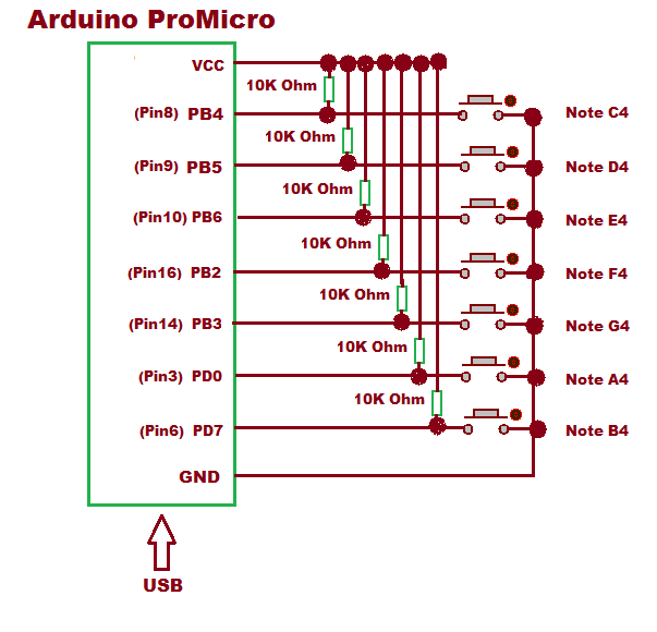
The project uses Arduino Pro Micro as the USB controller chip. A set of seven tactile switches are connected at the port B and D of the Arduino for generating seven different musical notes. The switches are connected at pins 2, 3, 4, 5 and 6 of Port B and pins 0 and 7 of Port D with following musical notes assigned to them.

Fig. 3: Table listing Arduino pins and respective Musical Notes
The Program code for the project is burnt to the Arduino Pro Micro using AVR Dude. The Arduino board is connected to the USB port of a PC by a USB cable.
HOW THE PROJECT WORKS
In this project, the USB protocol is implemented by the LUFA framework. For configuring the controller chip to work as a music keyboard, the MIDI Subclass of the Audio Class Driver of the LUFA framework will be used. The Audio Class 1.0 driver takes care of the transfers between the host device and the audio devices like microphone, speaker and USB Connect-able musical instruments.
When a USB device is attached to the host (PC), the host sends request for configuration details in the form of control transfer. The connected device has to respond with appropriate descriptors to get configured and ready for further operations. Only after configuration, the device can communicate with the host in the form of interrupt, isochronous or bulk transfers for executing the operations for which the device has been made. In case of MIDI keyboard, after configuring with the host device, it has to communicate with the host in the form of bulk transfers as the device will be actually sending music control information to the computer which will be saved to a temporary or permanent audio file for use by the desktop music synthesizer application. The process of identification and configuration of the device with the host is called enumeration.
UNDERSTANDING MUSICAL NOTES
The musical notes are used for the identification of the music. Like bits and bytes form the digital data, similarly musical notes together create the music. A musical note actually refers to a sound wave having specific frequency. The audible sound has frequency in range from 20 Hz to 20,000 Hz. The musical keyboards generate sound frequencies between 27.5 Hz to 4186 Hz. Between this range, specific frequencies are generated by the musical keyboards which are called the musical notes. Like the musical note A0 denotes 27.5 Hz frequency or 36.36 milliseconds period of sound wave. The note name for musical note can differ in different human languages. Like in English, the musical notes are represented by note names having alphabets A, B, C, D, E, F and G followed by a number. In musical terminology, the frequency of the musical note is referred by the term “Pitch”Another term associated with musical notes or music is volume. The volume refers to the amplitude of the sound wave and signifies the loudness of the sound. In musical terminology, the volume or amplitude of any musical note is referred by the term “velocity”MIDI and Musical Notes.
The MIDI protocol is used to exchange musical control information. In another way, this protocol does not transmit any sound signal, it just transmits the control information that is needed to regenerate the sound. In any MIDI data packet, the protocol transmits two control parameters – Pitch and Velocity of the sound signal to represent a musical note.
Pitch – It is a number between 0 and 127 that describes the frequency of the signal produced. Each pitch has its corresponding frequency. This means a total of 128 different frequency signals can be described by pitch, but not all are used in the actual implementation. For example, pitch number 21 is used to represent the frequency of 27.5 Hz.
Velocity – It is also a number between 0 and 127. It describes the Volume level or Amplitude of the sound produced. Higher velocity means louder sound.
A typical music keyboard has the following MIDI numbers representing the musical notes.

Fig. 4: Image showing MIDI numbers representing the musical notes on typical music keyboard
Of these standard musical notes, the device will generate following seven musical notes -:

Fig. 5: Table listing Arduino pins respective to standard musical notes
The device will generate musical notes having constant velocity value of 100.
The MIDI sub class implements Interface with more than one endpoint to exchange MIDI data. All endpoints use Bulk Transfer to exchange MIDI data with the host. The MIDI data is transmitted in a fixed size data packet of 32 bits (4 bytes). These packets are known as event packets. The below tables describe the contents of the packet.

Fig. 6: Table listing contents of the MIDI Data Packet
• Byte 0 – The Cable Number is the number for the Embedded MIDI jack. It can have a value from 0x0 to 0xF. The default value 0 is used generally. The Code Index Number classifies the MIDI data bytes.
• Byte 1 – In the upper nibble of this byte, the type of command or request is sent. The most common commands are Note On (0x9) and Note Off (0x8). The Note On command indicates that a note key has been pressed and Note Off command indicates that a note key has been released.
The lower nibble indicates the channel number at which data is exchanged. The channel number is used when different MIDI devices are connected to each other. Different channel number can be used by MIDI devices so that no intermixing of data happens and only the required device listens to the data. Total 16 channels can be used; 0x0 – 0xf.
• Byte 2 – In this byte, the data related to command indicated in Byte 1 is provided. For Note On and Note Off command, this byte contains pitch value between 0 and 127.
• Byte 3 – In this byte also, the data related to command indicated in Byte 1 is provided. For Note On and Note Off command, this byte contains velocity value between 0 and 127.
To implement a basic Music Keyboard, the firmware will generate the above event packet. The packet field values that will be transmitted by firmware are -:
• Byte 0 – 0x09 (for Note On) and 0x08 (for Note Off)
• Byte 1 – 0x91 (for Note On) and 0x81 (for Note Off). Channel 1 is used
• Byte 2 – Pitch value between 0 and 127
• Byte 3 – Velocity value of 1
The LUFA framework has MIDI class related modules in the LUFA-Source-Folder /LUFA/Drivers/USB/Class/Device folder. Other device class related module are also in the same folder. The LUFA framework has demo projects for different USB device classes in the LUFA-Source-FolderDemosDeviceClassDriver folder. For implementing the project, demo project for MIDI provided in the LUFA framework will be modified and complied.
The demo project for MIDI is in the LUFA-Source-FolderDemosDeviceClassDriverMIDI folder. The folder contains MIDI.c file which will be modified to implement the project.

Fig. 7: Screenshot of Musical Notes generated from AVR based USB MIDI Keyboard
How MIDI.c identifies device as Music Keyboard
The MIDI.c uses Keyboard_MIDI_Interface interface in MIDI_Device_USBTask() function which is being imported from the MIDIClassDevice.c (from LUFA-Source-Folder LUFADriversUSBClassDevice) to configure the device as music keyboard. The interface abstracts the low-level descriptor codes and identifies the device as music keyboard through a StreamingInterfaceNumber variable.
MIDI Specific Report Descriptors
Similar to any HID device, the MIDI subclass device also has to exchange data with the host which should be structured in the form of reports. The report descriptor defines the report structure. A report descriptor contains the information needed by host to determine the data format and how the data should be processed by the host. Therefore, a report descriptor basically structure the data that needs to be exchanged with the host according to the USB protocol.
For working like a MIDI device, the device also needs to respond with proper descriptors in response to the requests made by the host. An MIDI subclass device has the following descriptors associated with it -:
1) Device Descriptor
2) Configuration Descriptor
3) MIDIStreaming Interface Descriptors (Standard MS Interface Descriptor and Class-Specific MS Interface Descriptor)
4) MIDIStreaming Endpoint Descriptors (Standard MS Bulk Data Endpoint Descriptor, Class-Specific MS Bulk Data Endpoint Descriptor, Standard MS Transfer Bulk Data Endpoint Descriptor and Class-Specific MS Transfer Bulk Data Endpoint Descriptor)
The device descriptor and configuration descriptor for the MIDI device are defined in the descriptor.h file in the same folder with definitions in the descriptor.c file of the same folder. The MIDIStreaming Interface Descriptors and MIDIStreaming Endpoint descriptors are defined within the configuration descriptor. The descriptors get the usage report item values from the MIDIClassCommon.h (file located in LUFA-Source-FolderLUFADriversUSBClassCommon folder). The MIDI.c imports MIDI.h which imports USB.h. USB.h imports MIDICLass.h. In MIDIClass.h is imported MIDIClassDevice.h if the USB_CAN_BE_DEVICE is true for the controller chip to being a USB device not the host.
The MIDIClassDevice.h imports MIDIClassCommon.h where the MIDI Subclass device specific descriptor fields have been defined.

Fig. 8: Screenshot of MIDI Subclass device specific descriptor
The sub class protocols for the MIDI Class device are defined in the following manner.

Fig. 9: Screenshot of sub class protocols for the MIDI Class device
The device belongs to MIDI Streaming Subclass (0x03 hex code for protocol).
The event packet described above is defined in the MIDIClassCommon.h by the following structure.

Fig. 10: Screenshot of Event Packet in MIDIClassCommon.h File
The macros for MIDI commands that should be passed as Event Byte (Byte0) or Data1 Byte (Byte1) are defined by the following macros in the MIDIClassCommon.h.

Fig. 11: Screenshot of macros for MIDI commands in Event Packet of MIDIClassCommon.h File
Of these macros, only MIDI_COMMAND_NOTE_ON and MIDI_COMMAND_NOTE_OFF will be used.
The report item values defined for the above stated descriptors are taken from the “USB Device Class Definitions for MIDI devices” provided by the USB Implementers Forum. The Host can access these report descriptors by requesting the device using GET_REPORT request. This report is transmitted using Control Transfer Type of the USB protocol.
HOW THE DEVICE WORKS
The AVR microcontroller is programmed to sense input from the tactile switches based on which it transmits specific MIDI packets to the host computer on USB interface. On the Host PC end, the MIDI data will be collected and recorded by Software Synthesizer. The recorded data can be analyzed, modified or produced to an audio file. The demo code for MIDI given in the LUFA framework will be used to more or less extent as it is. Some minor modifications like commenting out unused features and detecting digital inputs to transmit specific MIDI packets will be done.
PROGRAMMING GUIDE
For building the project download the LUFA framework from the github.com. The demo project provided with the LUFA framework is modified to make the project. In the extracted LUFA zip file, open Demos/Device/ClassDriver/MIDI folder. The folder has the following files and folders.

Fig. 12: Screenshot of LUFA Library Folder on Windows
Of these, MIDI.h, MIDI.c and Makefile needs to be modified for this project. The modified files (provided at the bottom of the article in zip format) can also be downloaded from the engineersgarage and replaced with the original files.. Either open the files in WinAVR Studio or Notepad++ and modify original files or replace files with the already modified one. The modified or replaced MIDI.c needs to be compiled from within the LUFA’s Source folder to get the object code.
Modifying MIDI.h
The MIDI.h library file is imported in the MIDI.c file and includes a set of additional libraries and defines the constants and functions needed for the device operation. These include the additional libraries for the joystick, button and LEDs which should be commented out as the project is not using these features. So open MIDI.h and make the following changes -:
• Comment the #include library statements for Joystick.h, LEDS.h, and Buttons.h ( We are commenting these libraries as we are not using any joystick, buttons board and LED board)
• Comment the #define statements for LEDMASK_USB_NOTREADY, LEDMASK_USB_ENUMERATING, LEDMASK_USB_READY, LEDMASK_USB_ERROR
Save the file with changes.
Modifying MIDI.C file
Again in the MIDI.c, the code sections for Joystick, button board and LEDs need to be commented out. So open MIDI.c and make the following changes -:
• In the main loop, comment the LEDs_SetAllLEDs()
• In SetupHardware() function, comment the Joystick_Init(), LEDs_Init(), Buttons_Init()
• In EVENT_USB_Device_Connect() function, comment the LEDs_SetAllLEDs()
• In EVENT_USB_Device_Disconnect() function, comment LEDs_SetAllLEDs()
• In EVENT_USB_Device_ConfigurationChanged() function, comment the LEDs_SetAllLEDs()
In MIDI.c the main() function executes the functioning of the music keyboard. Inside the main function Port B and D where the tactile switches have been connected needs to be defined as input and all the pins of port B and D has to be raised to HIGH logic by default as the microcontroller will need to detect LOW logic for input from tactile switches, so add the following statements in the beginning of main() function.
In the main function, the following lines inside the for loop have been commented.
• MIDI_EventPacket_t ReceivedMIDIEvent
• While loop with its statements
These statements have been commented as they are used to get MIDI Data from Host. The device only needs to send data to the Host. For the implementation of the project, the MIDI packets will be managed from within the CheckJoystickMovement() function.
Inside the infinite for loop, the MIDI_Device_USBTask() function is called where Keyboard_MIDI_Interface interface is passed as parameter. The interface identifies the device as music keyboard and abstracts the low level program code specific to MIDI subclass protocol. The function is coming from the MIDIClassDevice.c module (located in LUFA/Drivers/USB/Class/Device/ folder) and is used for general management task for a given MIDI subclass interface, required for the correct operation of the interface. It should be called in the main program loop, before the master USB management task USB_USBTask(). The USB_USBTask() is the main USB management task. The USB driver requires this task to be executed continuously when the USB system is active (device attached in host mode, or attached to a host in device mode) in order to manage USB communications. The function is defined in USBTask.c (Located in LUFA-Source-FolderLUFADriversUSBCore folder).
In the CheckJoystickMovement() function, each key press will be detected by detecting LOW logic at the Arduino pins. Therefore, the codes for detecting joystick movement will be removed and variables to keep track of button status and button status change are declared. With each button press, specific values in MIDICommand and MIDIPitch variables are passed. These variables are used in the MIDI event which is defined as MIDIEvent object. The object is then used in MIDI_Device_SendEventPacket() function (The MIDI_Device_SendEventPacket() function is defined the MIDIClassDevice.c located in LUFA-Source-FolderLUFADriversUSBClassDevice folder). So, the CheckJoystickMovement() function will have the following body.
The velocity of each musical note is set to 100 by assigning value to the MIDIVelocity variable. In the body _BV() function is used to map the respective bit as a byte with only the respective bit changed in the returned byte. Save the file and create Make file for the project.
Modifying Make File
In the MIDI folder there is a make file that needs to be edited. The file can be edited using Notepad++. The following information needs to be edited -:
• MCU = atmega32u4
• ARCH = AVR8
• BOARD = LEONARDO
• F_CPU = 16000000
Save the file and exit. Now all the files are edited completely for the Music Keyboard Project.
Compiling MIDI.c
For compiling the source code, WinAVR Programmers Notepad or Arduino IDE can be used. Open the modified MIDI.c file and compile the code.
BURNING HEX CODE
The hex file is generated on compiling the MIDI.c file. For burning the object code to microcontroller open the Command Prompt, change the current directory to the directory containing the Hex file. This can be done using command: CD <address of the directory>. Now reset the Arduino and instantly run the command: : avrdude -v -p atmega32u4 -c avr109 -P COM20 -b 57600 -D -Uflash:w:MIDI.hex:i after replacing the COM Port with the recognized one.
If the uploading process is successful, the Arduino will be shown as LUFA MIDI Demo in the Device Manager. There is no need of installing any driver in the computer as Generic MIDI Subclass driver is used for the project implementation.
TESTING
For testing the device, Software Synthesizer needs to be installed in the Host or PC. The MIDI-OX software can be used to test if all the keys are working or not. To use the MIDI-OX software, first plug in the device and open the software. Then select LUFA MIDI as input device by opening Options->MIDI Devices. The status of the pressed key can be seen on Output Monitor window. Other Software that can be used to record MIDI data and convert it into audio signal is Anvil Studio.
More keys can also be added to the board and other musical notes can be added by coding additional MIDI packets in the project code.
In the next project – Atmega 32u4 Based USB EEPROM Reader, learn how to make an USB storage device and read and write data to an external EEPROM memory.
Project Source Code
###
/* LUFA Library Copyright (C) Dean Camera, 2015. dean [at] fourwalledcubicle [dot] com www.lufa-lib.org */ /* Copyright 2015 Dean Camera (dean [at] fourwalledcubicle [dot] com) Permission to use, copy, modify, distribute, and sell this software and its documentation for any purpose is hereby granted without fee, provided that the above copyright notice appear in all copies and that both that the copyright notice and this permission notice and warranty disclaimer appear in supporting documentation, and that the name of the author not be used in advertising or publicity pertaining to distribution of the software without specific, written prior permission. The author disclaims all warranties with regard to this software, including all implied warranties of merchantability and fitness. In no event shall the author be liable for any special, indirect or consequential damages or any damages whatsoever resulting from loss of use, data or profits, whether in an action of contract, negligence or other tortious action, arising out of or in connection with the use or performance of this software. */ /** file * * Main source file for the MIDI demo. This file contains the main tasks of * the demo and is responsible for the initial application hardware configuration. */ #include "MIDI.h" /** LUFA MIDI Class driver interface configuration and state information. This structure is * passed to all MIDI Class driver functions, so that multiple instances of the same class * within a device can be differentiated from one another. */ USB_ClassInfo_MIDI_Device_t Keyboard_MIDI_Interface = { .Config = { .StreamingInterfaceNumber = INTERFACE_ID_AudioStream, .DataINEndpoint = { .Address = MIDI_STREAM_IN_EPADDR, .Size = MIDI_STREAM_EPSIZE, .Banks = 1, }, .DataOUTEndpoint = { .Address = MIDI_STREAM_OUT_EPADDR, .Size = MIDI_STREAM_EPSIZE, .Banks = 1, }, }, }; /** Main program entry point. This routine contains the overall program flow, including initial * setup of all components and the main program loop. */ int main(void) { SetupHardware(); // PortB as input port DDRB = 0x00; // Make all pins of PortB high PORTB = 0xff; // PortD as input port DDRD = 0x00; // Make all pins of PortD high PORTD = 0xff; //LEDs_SetAllLEDs(LEDMASK_USB_NOTREADY); GlobalInterruptEnable(); for (;;) { CheckJoystickMovement(); /* MIDI_EventPacket_t ReceivedMIDIEvent; while (MIDI_Device_ReceiveEventPacket(&Keyboard_MIDI_Interface, &ReceivedMIDIEvent)) { if ((ReceivedMIDIEvent.Event == MIDI_EVENT(0, MIDI_COMMAND_NOTE_ON)) && (ReceivedMIDIEvent.Data3 > 0)) LEDs_SetAllLEDs(ReceivedMIDIEvent.Data2 > 64 ? LEDS_LED1 : LEDS_LED2); else LEDs_SetAllLEDs(LEDS_NO_LEDS); } */ MIDI_Device_USBTask(&Keyboard_MIDI_Interface); USB_USBTask(); } } /** Configures the board hardware and chip peripherals for the demo's functionality. */ void SetupHardware(void) { #if (ARCH == ARCH_AVR8) /* Disable watchdog if enabled by bootloader/fuses */ MCUSR &= ~(1 << WDRF); wdt_disable(); /* Disable clock division */ clock_prescale_set(clock_div_1); #elif (ARCH == ARCH_XMEGA) /* Start the PLL to multiply the 2MHz RC oscillator to 32MHz and switch the CPU core to run from it */ XMEGACLK_StartPLL(CLOCK_SRC_INT_RC2MHZ, 2000000, F_CPU); XMEGACLK_SetCPUClockSource(CLOCK_SRC_PLL); /* Start the 32MHz internal RC oscillator and start the DFLL to increase it to 48MHz using the USB SOF as a reference */ XMEGACLK_StartInternalOscillator(CLOCK_SRC_INT_RC32MHZ); XMEGACLK_StartDFLL(CLOCK_SRC_INT_RC32MHZ, DFLL_REF_INT_USBSOF, F_USB); PMIC.CTRL = PMIC_LOLVLEN_bm | PMIC_MEDLVLEN_bm | PMIC_HILVLEN_bm; #endif /* Hardware Initialization */ //Joystick_Init(); //LEDs_Init(); //Buttons_Init(); USB_Init(); } /** Checks for changes in the position of the board joystick, sending MIDI events to the host upon each change. */ void CheckJoystickMovement(void) { // Static variable to hold previous buttons status static uint8_t PrevButtonStatus = 0xff; // Initialise MIDI command to zero uint8_t MIDICommand = 0; // Variable to hold MIDI pitch value uint8_t MIDIPitch; /* Variable to store MIDI Velocity value * The default value of 100 is stored * Value between 0 and 127, can be stored * as per loudness or Volume Gain required */ uint8_t MIDIVelocity = 100; // Get button status for the buttons connected at PORTB and PORTD uint8_t button_status = (PINB & 0x7e) | (PIND & 0x81); // Store the changes in between the above scanned button status and the previous one uint8_t button_state_change = (button_status ^ PrevButtonStatus); // Set channel to 1 uint8_t Channel = 1; // check if the key for Note C4 has been pressed or released if (button_state_change & _BV(4)) { /* if key is pressed, store MIDI ON command * else, store MIDI OFF command */ if(!(button_status & _BV(4))) { MIDICommand = MIDI_COMMAND_NOTE_ON; MIDIPitch = 0x3C; // Pitch value for Note C4 } else { MIDICommand = MIDI_COMMAND_NOTE_OFF; MIDIPitch = 0x3C; // Pitch value for Note C4 } } // check if the key for Note D4 has been pressed or released if (button_state_change & _BV(5)) { if(!(button_status & _BV(5))) { MIDICommand = MIDI_COMMAND_NOTE_ON; MIDIPitch = 0x3E; // Pitch value for Note D4 } else { MIDICommand = MIDI_COMMAND_NOTE_OFF; MIDIPitch = 0x3E; // Pitch value for Note D4 } } // check if the key for Note E4 has been pressed or released if (button_state_change & _BV(6)) { if(!(button_status & _BV(6))) { MIDICommand = MIDI_COMMAND_NOTE_ON; MIDIPitch = 0x40; // Pitch value for Note E4 } else { MIDICommand = MIDI_COMMAND_NOTE_OFF; MIDIPitch = 0x40; // Pitch value for Note E4 } } // check if the key for Note F4 has been pressed or released if (button_state_change & _BV(2)) { if(!(button_status & _BV(2))) { MIDICommand = MIDI_COMMAND_NOTE_ON; MIDIPitch = 0x41; // Pitch value for Note F4 } else { MIDICommand = MIDI_COMMAND_NOTE_OFF; MIDIPitch = 0x41; // Pitch value for Note F4 } } // check if the key for Note G4 has been pressed or released if (button_state_change & _BV(3)) { if(!(button_status & _BV(PB3))) { MIDICommand = MIDI_COMMAND_NOTE_ON; MIDIPitch = 0x43; // Pitch value for Note G4 } else { MIDICommand = MIDI_COMMAND_NOTE_OFF; MIDIPitch = 0x43; // Pitch value for Note G4 } } // check if the key for Note A4 has been pressed or released if (button_state_change & _BV(0)) { if(!(button_status & _BV(PD0))) { MIDICommand = MIDI_COMMAND_NOTE_ON; MIDIPitch = 0x45; // Pitch value for Note G4 } else { MIDICommand = MIDI_COMMAND_NOTE_OFF; MIDIPitch = 0x45; // Pitch value for Note G4 } } // check if the key for Note B4 has been pressed or released if (button_state_change & _BV(7)) { if(!(button_status & _BV(7))) { MIDICommand = MIDI_COMMAND_NOTE_ON; MIDIPitch = 0x47; // Pitch value for Note B4 } else { MIDICommand = MIDI_COMMAND_NOTE_OFF; MIDIPitch = 0x47; // Pitch value for Note B4 } } // If any key is pressed or released, prepare the Event Packet if (MIDICommand) { MIDI_EventPacket_t MIDIEvent = (MIDI_EventPacket_t) { .Event = MIDI_EVENT(0, MIDICommand), .Data1 = MIDICommand | Channel, .Data2 = MIDIPitch, .Data3 = MIDIVelocity, }; MIDI_Device_SendEventPacket(&Keyboard_MIDI_Interface, &MIDIEvent); MIDI_Device_Flush(&Keyboard_MIDI_Interface); } PrevButtonStatus = button_status; } /** Event handler for the library USB Connection event. */ void EVENT_USB_Device_Connect(void) { //LEDs_SetAllLEDs(LEDMASK_USB_ENUMERATING); } /** Event handler for the library USB Disconnection event. */ void EVENT_USB_Device_Disconnect(void) { //LEDs_SetAllLEDs(LEDMASK_USB_NOTREADY); } /** Event handler for the library USB Configuration Changed event. */ void EVENT_USB_Device_ConfigurationChanged(void) { bool ConfigSuccess = true; ConfigSuccess &= MIDI_Device_ConfigureEndpoints(&Keyboard_MIDI_Interface); //LEDs_SetAllLEDs(ConfigSuccess ? LEDMASK_USB_READY : LEDMASK_USB_ERROR); } /** Event handler for the library USB Control Request reception event. */ void EVENT_USB_Device_ControlRequest(void) { MIDI_Device_ProcessControlRequest(&Keyboard_MIDI_Interface); }###
Circuit Diagrams
Project Datasheet
Project Video
Filed Under: Electronic Projects
Filed Under: Electronic Projects

Questions related to this article?
👉Ask and discuss on EDAboard.com and Electro-Tech-Online.com forums.
Tell Us What You Think!!
You must be logged in to post a comment.