How a generic mouse is made was explained in the Atmega 32u4 Based Generic USB Mouse Project. In this project a wireless mouse will be designed. For making a wireless mouse, there will be two circuits involved in the project – a transmitter circuit which will have a keypad included for getting the user input and a receiver circuit that will connect with the PC through USB port. The two circuits will connect wirelessly using NRF24lO1 module. The NRF module is a Wireless Transceiver that works on 2.4 GHz ISM (Industrial Scientific Medical) band. It is manufactured by Nordic Semiconductors. The transmitter section will have Arduino Mega as the controller board. At the receiver section, the computation will be handled by two controller boards – Arduino UNO and Arduino Pro Micro, each having their own computational roles. At the end Arduino Pro Micro will connect with the USB port of the PC where the 8-bit USB AVR – Atmega 32u4 will work as the USB controller chip. The Arduino Pro Micro will use AVR based Lightweight USB Framework (LUFA) as the firmware for implementing the USB protocol in the end phase of the project execution.
Usually the USB mouse has optical sensor to detect the desired direction of navigation across the screen. Instead of using optical sensor, the project will use tactile switches to input direction of cursor movement and mouse click. The Arduino Pro Micro will use HID device driver class of LUFA framework for mouse which will be modified to implement the project. With the use of LUFA firmware on Arduino Pro Micro, the device driver code to implement USB protocol is not needed to be written explicitly. The project works similar to any USB mouse having wireless connectivity and has buttons for the following Inputs – :
• Move Pointer Left
• Move Pointer Right
• Move Pointer Upwards
• Move Pointer Down
• Right Click
• Left Click
The transmitter circuit of the project uses tactile switches for mouse inputs, Arduino Mega for generating HID data of mouse device and NRF24LO1 for wireless connectivity. The receiver circuit of the project will use NRF24LO1 for receiving HID mouse data wirelessly, Arduino UNO to fetch and pass the HID data forward, Arduino Pro Micro to analyze HID data and prepare HID mouse specific data reports, and USB cable to connect with the personal computer.

Fig. 1: Image showing push buttons connected at Transmitter Side of Arduino based DIY Wireless USB Mouse
PREREQUISITES
This project is based on Arduino Pro Micro, Arduino Mega and Arduino UNO which have AVR microcontrollers on board. In order to understand this project, one must have basic knowledge of the AVR microcontrollers and the embedded C programming for AVRs. WinAVR Studio is used to write, edit and compile the project code, so closely following the project shall require familiarizing with the above stated IDE as well. Though LUFA framework takes care of implementing the USB protocol on Arduino Pro Micro and has APIs to abstract the lower level codes, understanding USB protocol is recommended to understand how actually the project is working. In fact, if anyone has already worked on some other microcontroller and have some experience of working on electronic circuits, it will not be much pain to understand and follow this project. The project is based on getting input from the GPIO pins of AVR MCU, transmitting data through SPI, interfacing wireless module with Arduino(s) and modifying the LUFA device driver for mouse functionality.
COMPONENTS REQUIRED
1. Arduino Pro Micro
2. Arduino Mega
3. Arduino UNO
4. Breadboard
5. Connecting wires
6. Push buttons
7. Micro USB cable
8. 10K resistors
9. NRF24LO1 Transmitter and Receiver
SOFTWARE TOOLS REQUIRED
1. WinAVR Studio
2. AVR Dude
BLOCK DIAGRAM

Fig. 2: Block Diagram of Arduino based DIY Wireless USB Mouse
CIRCUIT CONNECTIONS
The project will have two circuits – Transmitter Circuit and the Receiver Circuit. The Transmitter will have following hardware blocks – :
• Keys – The push buttons will be used for getting directional and button press inputs. There will be six switches for the following functions – Left Movement, Right Movement, Upward Movement, Downward Movement, Right Click and Left Click. The Push buttons will be attached to Arduino Mega via Digital Input/Output pins. The switches will be interfaced to the pins of the Arduino Mega in the following manner.

Fig. 3: Table listing Arduino pins and their respective functions as USB Mouse
The tactile switches are connected between the pins and the ground. The pins by default are connected to VCC and receive a HIGH logic. Pressing a tactile switch changes the status at the respective pin to LOW by short circuiting to the ground.
• Arduino Mega – The Arduino Mega will be the controller board at the transmitter end. The NRF will be interfaced with Arduino to add the wireless functionality. Push buttons that will work as input keys will be attached to the GPIO pins of the Arduino. The Arduino Mega has more input pins than other boards, which makes it suitable for connecting large number of keys. Therefore, on Arduino Mega, the project can be expanded from four keys to more number of keys to include additional functionality.
• NRF – The NRF24LO1 will be interfaced with the Arduino Mega via SPI (Serial Peripheral Interface). It will be used to transmit data wirelessly to receiver. The NRF module will be interfaced to the Arduino Mega by connecting the pins in the following manner – :

Fig. 4: Table listing circuit connections between Arduino Mega and NRF Module on Transmitter Circuit
The Receiver circuit of the project will have the following hardware blocks -:
• NRF – The NRF24LO1 will receive the Data Packet from the Transmitter via wireless communication. It will then feed the packet to the Arduino UNO via SPI protocol. The receiver side NRF module will be interfaced with the Arduino UNO by connecting their pins in the following manner -:

Fig. 5: Table listing circuit connections between Arduino Mega and NRF Module on Receiver Circuit
• Arduino UNO – The Arduino UNO will collect Data Packet from NRF and will provide it to Atmega32u4 microcontroller on Arduino Pro Micro via UART serial communication. The Arduino UNO will act as intermediate device that will convert wireless protocol into serial protocol. The Arduino UNO and Arduino Pro Micro will be connected via UART pins in the following manner -:

Fig. 6: Table listing circuit connections between Arduino Uno and Arduino Pro Micro
• Arduino Pro Micro – The Arduino Pro Micro has the Atmega 32u4 as the sitting MCU. The microcontroller will take Data Packet from the Arduino UNO and transmit relevant mouse specific HID reports according to the USB protocol to the PC. It will connect to the USB port of a PC by a USB cable.
The Program code for the project will be burnt to the Arduino Pro Micro, Arduino UNO and Arduino Mega using AVR Dude.
HOW THE PROJECT WORKS
The functioning of the project involves three stages – :
1) Detection of key press and wireless transmission of data containing HID report values – This stage is handled by the Arduino Mega on the transmitter circuit of the project. The Arduino Mega has the program code to detect key press by detecting LOW logic at the pins to which tactile switches have been interfaced and pass a 3-byte code to the NRF module for wireless transmission. The Arduino Mega pass the 3-byte data to NRF module using SPI interface. Check out the program code of Arduino Mega to learn how key press is detected and accordingly 3-byte custom data is passed through SPI.
2) Wireless reception of data containing HID report values and passing it to Arduino Pro Micro – In the next stage, the 3-byte data received from the wireless module is read by the Arduino UNO and passed to the Arduino Pro Micro through UART interface. The Arduino UNO connects with the NRF module by SPI interface. Check out the program code to learn how Arduino UNO receives 3-byte data through SPI interface and passes it to Arduino Pro Micro by the UART interface.

Fig. 7: Prototype of Arduino based DIY Wireless USB Mouse
3) Analysis of 3-byte data to fetch mouse report items and transmit HID data report specific to mouse device to the PC – The 3-byte data is received by the Arduino Pro Micro from the UART interface. The program code on Arduino Pro Micro is built on LUFA framework and has the demo project of mouse modified to detect mouse movement and button click from data received from UART and transmit mouse specific HID reports to the PC. For configuring the controller chip on Arduino Pro Micro to work as USB mouse, the HID Class Driver of the LUFA framework is used. The Human Interface Device (HID) class takes care of the transfers between the host device and the human controlled USB peripherals like USB Keyboard, Mouse or Joystick. Being a USB device on connecting with the PC, the Arduino Pro Micro has to get enumerated as HID mouse.
A mouse is an HID class USB device and LUFA framework has HID class related module in the LUFA-Source-Folder /LUFA/Drivers/USB/Class/Device folder. Other device class related module are also in the same folder. The LUFA framework has demo projects for different USB device classes in the LUFA-Source-FolderDemosDeviceClassDriver folder. For implementing the project, demo project for mouse provided in the LUFA framework will be modified and complied. The demo project for mouse is in the LUFA-Source-FolderDemosDeviceClassDriverMouse folder. The folder contains mouse.c file which will be modified to make the wireless mouse.
How Mouse.c identifies HID device being Mouse
The mouse.c uses Mouse_HID_Interface interface in HID_Device_USBTask() function which is being imported from the HIDDeviceClass.c (file located in LUFA-Source-Folder LUFADriversUSBClassDevice) to configure the device as mouse. The interface abstracts the low-level descriptor codes and identifies the device as mouse through an InterfaceNumber variable.
Usage and Data Report Descriptors
Any HID device has to exchange data with the host which should be structured in the form of reports. The report descriptor defines the report structure. A report descriptor contains the information needed by host to determine the data format and how the data should be processed by the host. Therefore, a report descriptor basically structure the data that needs to be exchanged with the host according to the USB protocol.
The Usage or Feature report contains the information related to the features of the device. For example, a Mouse feature report generally contains information about number of buttons used, number of axis, scroll wheel, size of Data Report, minimum/maximum movement etc. In other words, this report informs the Host about the type of features needed in the device. The Host can access this report by requesting the device using GET_REPORT request. This report is transmitted using Control Transfer Type of the USB protocol.
From Where Mouse.C gets the USAGE and Data Report Descriptors
In the LUFA framework’s demo project for mouse, descriptor.c file is imported in mouse.c to send the relevant usage and data report descriptors to the host device. The descriptor.c defines a MouseReport[] structure which is used in the CALLBACK_HID_Device_CreateHIDReport() function of the mouse.c to generate mouse specific usage and data report descriptors. Inside descriptor.c the MouseReport[] structure has the values returned by HID_DESCRIPTOR_MOUSE() function. The HID_DESCRIPTOR_MOUSE() is defined in HIDClassCommon.h (located in LUFA-Source-FolderLUFADriversUSBClassCommon folder). The mouse.c imports usb.h which imports HIDCLass.h. In HIDClass.h is imported HIDClassDevice.h if the USB_CAN_BE_DEVICE is true for the controller chip to being a USB device not the host. The HIDClassDevice.h imports HIDClassCommon.h where the HID device specific descriptor fields have been defined
Usage and Data Reports
To learn about the usage and data reports specific to mouse device refer to the Atmega 32u4 Based Generic USB Mouse Project. For understanding this project it is important to understand data report of the mouse. The Data Report contains the data that needs to be transmitted to the Host. It contains data related to the features selected via the Usage Report. The data input report for mouse consist of 3 bytes of which byte0 is used to indicate button click, byte1 is used to indicate X axis movement as signed integer and byte2 is used to indicate Y axis movement as signed integer. The field values specific to data report for mouse are organised in the following manner – :

Fig. 8: Table listing Usage and Data Reports for USB Mouse
For the project implementation, a 3-byte data report needs to be send to the PC. The required 3-byte data is received wirelessly from the transmitter circuit of the project by the receiver circuit.
The main() function and the CALLBACK_HID_Device_CreateHIDReport() function of the mouse.c are modified to detect 3-byte data and send relevant data reports to the PC.
PROGRAMMING GUIDE
1) Program Code of Arduino Mega – The Arduino Mega detects the key press by detecting LOW logic at its pins and transmits relevant mouse data report items by passing 3-byte data to the NRF module on SPI interface.
First the libraries for SPI and NRF modules are imported.
Then, two arrays are declared to hold the addresses of the SPI transmitter and receiver pipes. A three bytes long integer variable is declared to hold the value of mouse data report items that should be passed to the NRF transmitter.
The Arduino Mega pins are assigned constant names.
A setup function is called in which the Arduino pins where the tactile switches are connected are configured as digital input. The SPI interface is initialized using standard radio.begin() function and the pipe address is set to LOW. The transmitter address is assigned to the pipe address by using radio.openWritingPipe() function.
A loop() function is called in which, first the 3-byte data that has to be transmitted is set to 0 and by detecting respective key press is assigned specific mouse data report item values.
If there is data available for transmission it is passed to NRF module on SPI interface using radio.write() function. The function accepts first parameter as pointer to the data and second parameter as the size of the data that has to be passed.
This completes the program code on Arduino Mega.
2) Program Code of Arduino UNO – The Arduino UNO reads the 3-byte data coming from the NRF module on SPI interface and pass it to the Arduino Pro Micro on UART interface.
First the libraries for SPI and NRF modules are imported.
Then, two arrays are declared to hold the addresses of the SPI transmitter and receiver pipes. A three bytes long integer variable is declared to hold the value of 3-byte data received from the NRF module. Also, three single byte integer variables are declared to hold the values of mouse data report items seperately.
A setup function is called in which the baud rate for serial communication on UART is set using Serial.begin() function. The SPI interface is initialized using standard radio.begin() function and the pipe address is set to LOW. The receiver address (SPI) is assigned to the pipe address by using radio.openReadingPipe() function. The data from the receiver pin of SPI is read using radio.startListening() function.
A loop() function is called in which the data availability is checked and if 3-byte data is successfully received, mouse data report items are separated in the variables declared for the respective purposes. The values of the variables holding report item respective to button, X and Y movement are passed serially on UART to the Arduino Pro Micro.
This completes the program code on Arduino UNO.
3) Program Code of Arduino Pro Micro – For programming the Arduino Pro Micro, download the LUFA framework from the github.com. The demo project provided with the LUFA framework is modified to implement the mouse specific HID class driver. In the extracted LUFA zip file, open Demos/Device/ClassDriver/Mouse folder. The folder has the following files and folders.

Fig. 9: Screenshot of LUFA Library Folder on Windows
Of these, Mouse.h, Mouse.c and Makefile needs to be modified for this project. The modified files (provided at the bottom of the article in zip format) can also be downloaded from the engineersgarage and replaced with the original files. Either open the files in WinAVR Studio or Notepad++ and modify original files or replace files with the already modified one. The modified or replaced Mouse.c needs to be compiled from within the LUFA’s Source folder to get the object code of Arduino Pro Micro.
Modifying Mouse.h
The Mouse.h library file is imported in the mouse.c file and includes a set of additional libraries and defines the constants and functions for the mouse device. These include the additional libraries for the joystick, button and LEDs which should be commented out as the project is not using optical sensors, LEDs or click buttons of typical mouse. So open Mouse.h and make the following changes – :
• Comment the #include library statements for Joystick.h, LEDS.h, and Buttons.h
• Comment the #define statements for LEDMASK_USB_NOTREADY, LEDMASK_USB_ENUMERATING, LEDMASK_USB_READY, LEDMASK_USB_ERROR
Save the file with changes.
Modifying Mouse.C file
Again in the Mouse.c, the code sections for Joystick, button board and LEDs need to be commented out. So open mouse.c and make the following changes -:
• In the main loop, comment the LEDs_SetAllLEDs()
• In SetupHardware() function, comment the Joystick_Init(), LEDs_Init(), Buttons_Init()
• In EVENT_USB_Device_Connect() function, comment the LEDs_SetAllLEDs()
• In EVENT_USB_Device_Disconnect() function, comment LEDs_SetAllLEDs()
• In EVENT_USB_Device_ConfigurationChanged() function, comment the LEDs_SetAllLEDs()
In Mouse.c, first uart.h has to be included. So add the following line below include statement of Mouse.h.
In the main() function, UART also needs to be initialized by using uart_init() function so add the following lines to the main() function of the Mouse.c.
Inside the infinite for loop the HID_Device_USBTask() function is called where Mouse_HID_Interface interface is passed as parameter. The interface identifies the device as mouse and abstracts the low level program code specific to mouse HID class. The function is coming from the HIDClassDevice.c module (located in LUFA/Drivers/USB/Class/Device/HIDClassDevice.c) and is used for general management task for a given HID class interface, required for the correct operation of the interface. It should be called in the main program loop, before the master USB management task USB_USBTask(). The USB_USBTask() is the main USB management task. The USB driver requires this task to be executed continuously when the USB system is active (device attached in host mode, or attached to a host in device mode) in order to manage USB communications. The function is defined in USBTask.c (Located in LUFA-Source-FolderLUFADriversUSBCore folder).
For holding the data report items extracted from the received 3-byte data, three global variables need to be declared along with a counter to trace position of byte in the received data. The ISR (Interrupt Service Routine) will be executed when any serial data is received.
The ISR that needs to be added in the source code is -:
For creating Mouse Data report CALLBACK_HID_Device_CreateHIDReport() needs to be modified. The default file has the function body to detect joystick movement and click on button board.

Fig. 10: Screenshot of CALLBACK_HID_Device_CreateHIDReport Function in LUFA Library
If there is any mouse report item extracted in the byte0, byte1 or byte 2 variables, it has to be passed into the HID data report of mouse device. So replace the body of the function with the following code -:
Save the file and create Make file for the project.
Modifying Make File
In the Mouse folder there will be a make file that needs to be edited. The file can be edited using Notepad++. The following information needs to be edited – :
• MCU = atmega32u4
• ARCH = AVR8
• BOARD = LEONARDO
• F_CPU = 16000000
Save the file and exit. Now all the files are edited completely for the basic HID Mouse application.
Compiling Mouse.c
For compiling the source code, we will use WinAVR Programmers Notepad. Open the modified Mouse.c file and compile the code.
BURNING HEX CODE
The hex file is generated on compiling the mouse.c file. For burning the object code to microcontroller open the Command Prompt, change the current directory to the directory containing the Hex file. This can be done using command: CD <address of the directory>. Now reset the Arduino and instantly run the command: avrdude -v -p atmega32u4 -c avr109 -P COM20 -b 57600 -D -Uflash:w:Mouse.hex:i after replacing the COM Port with the recognized one.
If the uploading process is successful, the Arduino will be shown as HID Mouse in the Device Manager. There is no need of installing any driver in the computer as Generic HID Mouse is used for the project implementation. Use the buttons on transmitter circuit to test the project working as wireless mouse.
In the next project – Atmega 32u4 Based USB Microphone, learn how to make a USB pluggable microphone that will record audio and save it to the PC.
Project Source Code
###
/* LUFA Library Copyright (C) Dean Camera, 2015. dean [at] fourwalledcubicle [dot] com www.lufa-lib.org */ /* Copyright 2015 Dean Camera (dean [at] fourwalledcubicle [dot] com) Permission to use, copy, modify, distribute, and sell this software and its documentation for any purpose is hereby granted without fee, provided that the above copyright notice appear in all copies and that both that the copyright notice and this permission notice and warranty disclaimer appear in supporting documentation, and that the name of the author not be used in advertising or publicity pertaining to distribution of the software without specific, written prior permission. The author disclaims all warranties with regard to this software, including all implied warranties of merchantability and fitness. In no event shall the author be liable for any special, indirect or consequential damages or any damages whatsoever resulting from loss of use, data or profits, whether in an action of contract, negligence or other tortious action, arising out of or in connection with the use or performance of this software. */ /** file * * Main source file for the Mouse demo. This file contains the main tasks of * the demo and is responsible for the initial application hardware configuration. */ #include "Mouse.h" #include "uart.h" /** Buffer to hold the previously generated Mouse HID report, for comparison purposes inside the HID class driver. */ static uint8_t PrevMouseHIDReportBuffer[sizeof(USB_MouseReport_Data_t)]; /** LUFA HID Class driver interface configuration and state information. This structure is * passed to all HID Class driver functions, so that multiple instances of the same class * within a device can be differentiated from one another. */ USB_ClassInfo_HID_Device_t Mouse_HID_Interface = { .Config = { .InterfaceNumber = INTERFACE_ID_Mouse, .ReportINEndpoint = { .Address = MOUSE_EPADDR, .Size = MOUSE_EPSIZE, .Banks = 1, }, .PrevReportINBuffer = PrevMouseHIDReportBuffer, .PrevReportINBufferSize = sizeof(PrevMouseHIDReportBuffer), }, }; //variable to hold received byte0 volatile uint8_t byte0 = 0; //variable to hold received byte1 volatile uint8_t byte1 = 0; //variable to hold received byte2 volatile uint8_t byte2 = 0; // counter variable to indicate the position of byte volatile uint8_t counter = 0; /** Main program entry point. This routine contains the overall program flow, including initial * setup of all components and the main program loop. */ int main(void) { SetupHardware(); /* enable the uart communication * with 57600 bps */ uart_init(16); //LEDs_SetAllLEDs(LEDMASK_USB_NOTREADY); GlobalInterruptEnable(); for (;;) { HID_Device_USBTask(&Mouse_HID_Interface); USB_USBTask(); } } /** Configures the board hardware and chip peripherals for the demo's functionality. */ void SetupHardware(void) { #if (ARCH == ARCH_AVR8) /* Disable watchdog if enabled by bootloader/fuses */ MCUSR &= ~(1 << WDRF); wdt_disable(); /* Disable clock division */ clock_prescale_set(clock_div_1); #elif (ARCH == ARCH_XMEGA) /* Start the PLL to multiply the 2MHz RC oscillator to 32MHz and switch the CPU core to run from it */ XMEGACLK_StartPLL(CLOCK_SRC_INT_RC2MHZ, 2000000, F_CPU); XMEGACLK_SetCPUClockSource(CLOCK_SRC_PLL); /* Start the 32MHz internal RC oscillator and start the DFLL to increase it to 48MHz using the USB SOF as a reference */ XMEGACLK_StartInternalOscillator(CLOCK_SRC_INT_RC32MHZ); XMEGACLK_StartDFLL(CLOCK_SRC_INT_RC32MHZ, DFLL_REF_INT_USBSOF, F_USB); PMIC.CTRL = PMIC_LOLVLEN_bm | PMIC_MEDLVLEN_bm | PMIC_HILVLEN_bm; #endif /* Hardware Initialization */ //Joystick_Init(); //LEDs_Init(); //Buttons_Init(); USB_Init(); } /** Event handler for the library USB Connection event. */ void EVENT_USB_Device_Connect(void) { //LEDs_SetAllLEDs(LEDMASK_USB_ENUMERATING); } /** Event handler for the library USB Disconnection event. */ void EVENT_USB_Device_Disconnect(void) { //LEDs_SetAllLEDs(LEDMASK_USB_NOTREADY); } /** Event handler for the library USB Configuration Changed event. */ void EVENT_USB_Device_ConfigurationChanged(void) { bool ConfigSuccess = true; ConfigSuccess &= HID_Device_ConfigureEndpoints(&Mouse_HID_Interface); USB_Device_EnableSOFEvents(); //LEDs_SetAllLEDs(ConfigSuccess ? LEDMASK_USB_READY : LEDMASK_USB_ERROR); } /** Event handler for the library USB Control Request reception event. */ void EVENT_USB_Device_ControlRequest(void) { HID_Device_ProcessControlRequest(&Mouse_HID_Interface); } /** Event handler for the USB device Start Of Frame event. */ void EVENT_USB_Device_StartOfFrame(void) { HID_Device_MillisecondElapsed(&Mouse_HID_Interface); } /** HID class driver callback function for the creation of HID reports to the host. * * param[in] HIDInterfaceInfo Pointer to the HID class interface configuration structure being referenced * param[in,out] ReportID Report ID requested by the host if non-zero, otherwise callback should set to the generated report ID * param[in] ReportType Type of the report to create, either HID_REPORT_ITEM_In or HID_REPORT_ITEM_Feature * param[out] ReportData Pointer to a buffer where the created report should be stored * param[out] ReportSize Number of bytes written in the report (or zero if no report is to be sent) * * return Boolean c true to force the sending of the report, c false to let the library determine if it needs to be sent */ bool CALLBACK_HID_Device_CreateHIDReport(USB_ClassInfo_HID_Device_t* const HIDInterfaceInfo, uint8_t* const ReportID, const uint8_t ReportType, void* ReportData, uint16_t* const ReportSize) { USB_MouseReport_Data_t* MouseReport = (USB_MouseReport_Data_t*)ReportData; // add the bytes in data report MouseReport->Button = byte0; /* check if byte1 is 0x81 * 0x81 indicates -1 */ if(byte1 == 0x81) MouseReport->X = -1; else MouseReport->X = byte1; /* check if byte2 is 0x81 * 0x81 indicates -1 */ if(byte2 == 0x81) MouseReport->Y = -1; else MouseReport->Y = byte2; // reset the bytes byte0 = 0; byte1 = 0; byte2 = 0; *ReportSize = sizeof(USB_MouseReport_Data_t); return true; } /** HID class driver callback function for the processing of HID reports from the host. * * param[in] HIDInterfaceInfo Pointer to the HID class interface configuration structure being referenced * param[in] ReportID Report ID of the received report from the host * param[in] ReportType The type of report that the host has sent, either HID_REPORT_ITEM_Out or HID_REPORT_ITEM_Feature * param[in] ReportData Pointer to a buffer where the received report has been stored * param[in] ReportSize Size in bytes of the received HID report */ void CALLBACK_HID_Device_ProcessHIDReport(USB_ClassInfo_HID_Device_t* const HIDInterfaceInfo, const uint8_t ReportID, const uint8_t ReportType, const void* ReportData, const uint16_t ReportSize) { // Unused (but mandatory for the HID class driver) in this demo, since there are no Host->Device reports } /* Interrupt Service Routine to capture the Serially received data * Store the received daa into corresponding variables */ ISR(USART1_RX_vect) { /* if this is the zeroth byte of the data packet * store the byte0 and update the counter * else if it is the first byte * store the byte1 and update the counter * else store second byte and reset the counter */ if(counter == 0) { byte0 = UDR1; // get data from rx counter = 1; // update counter } else if(counter == 1) { byte1 = UDR1; // get data from rx counter = 2; // update counter } else { byte2 = UDR1; // get data from rx counter = 0; // update counter } }###
Circuit Diagrams
| Circuit-Diagram-Receiver-Arduino-Based-DIY-Wireless-USB-Mouse | 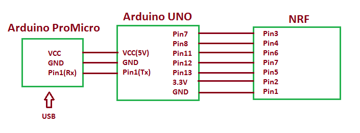 |
| Circuit-Diagram-Arduino-Based-DIY-Wireless-USB-Mouse | 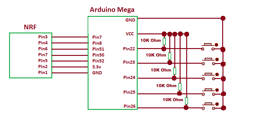 |
Project Datasheet
Project Video
Filed Under: Electronic Projects
Filed Under: Electronic Projects

Questions related to this article?
👉Ask and discuss on EDAboard.com and Electro-Tech-Online.com forums.
Tell Us What You Think!!
You must be logged in to post a comment.