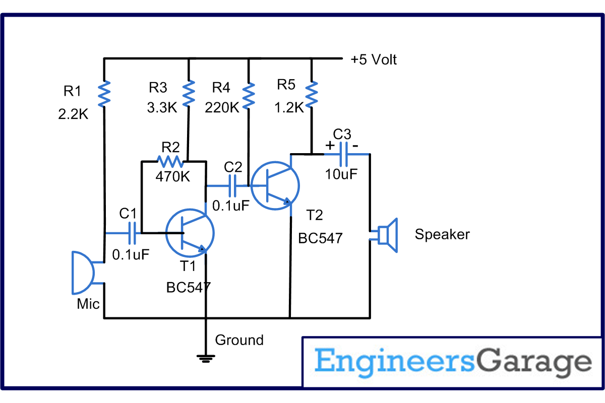
In several cases the sound generated is not clearly audible and hence it is required to increase the intensity level so that it can be further used. This audio amplifier circuit diagram based project demonstrates the principle and operation of a simple sound amplifier. The circuit is divided into three parts:
1.Sensor,
2.Amplifier, and
3. Output.
Sensor converts the physical characteristics of sound into electrical pulses, which is amplified by the amplifier unit.
The amplified output is obtained across the speaker. This circuit finds applications in security systems and as intermediate circuit to sense/amplify sound signals.
The audio amplifier circuit diagram is based on condenser mic which is used as a sensor to sense the audio signals and convert them to electrical pulses. The output of the mic is passed to Transistor T1 through a capacitor C1. The purpose of capacitor C1 is to block the DC components. Resistor
R1 is used to provide the necessary biasing to the condenser microphone. Transistor T1 is used in the collector to base biasing configuration. This is achieved through resistance R2, which provides negative feedback to the base of T1. The output of T1 appears across R3, which is the input to T2. The necessary filtering is provided by the capacitor C2. Transistor T2 is biased in the fixed bias configuration. The base is biased by the resistor R4. The output of T2 appears across the load resistor R5. The capacitor C3 helps in filtering the noise at the output end. The output appears across an 8 , ½ watt speaker.
Circuit Diagrams
Project Components
Filed Under: Electronic Projects


Questions related to this article?
👉Ask and discuss on EDAboard.com and Electro-Tech-Online.com forums.
Tell Us What You Think!!
You must be logged in to post a comment.