● Whenever we have to use washroom especially in night we have to on the light when we enter and we have to off the light when we leave. And sometimes we forget to off the light as we are in the middle of the sleep or because of any other reason. This lead to wastage of energy and money. Hence to resolve this problem you can assemble this easy circuit.
● This circuit can easily be installed in railway stations, restaurants and malls because in such places no body care about electricity wastage and there is no body to off the lights. This leads to wastage of resources.
● Important feature of this circuit is it will automatically on the lights when you close the door of the washroom and off the light automatically when the door is open again. So there is no need to worry about on and off the light. And it will also help you to reduce the power wastage and reduces your electricity bill.
[[wysiwyg_imageupload:11095:]]
Fig. 1: Prototype of Automatic Washroom Light Controller Circuit on Breadboard
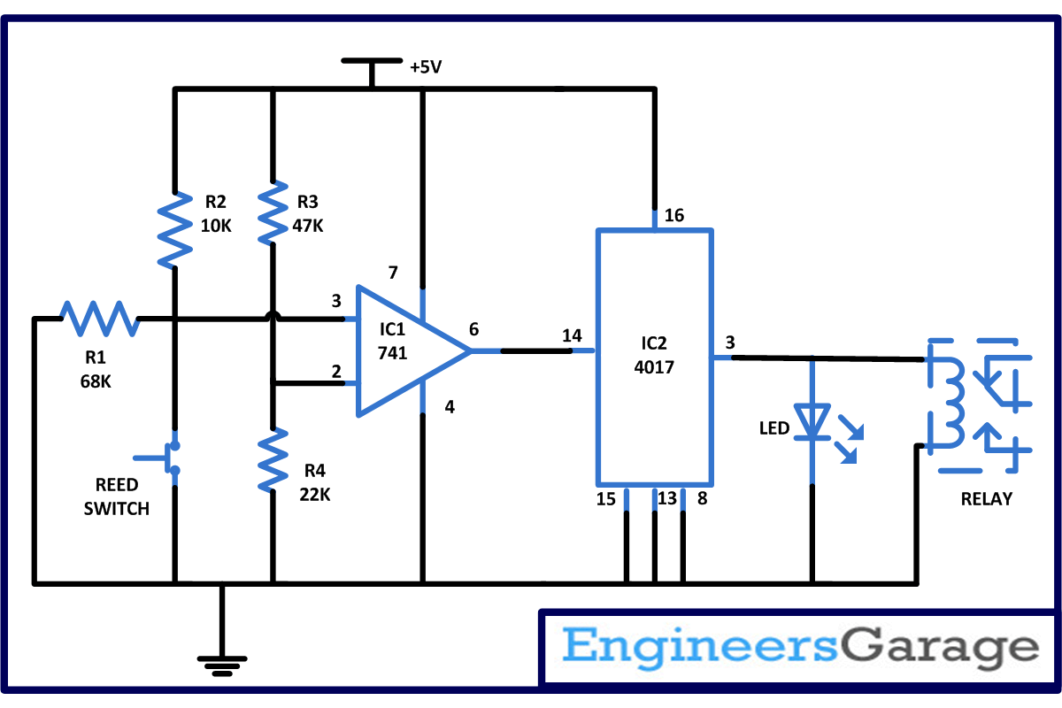
This automatic washroom light controller circuit is based on two IC namely uA741 which work as a comparator and CD4017 which is a CMOS counter/ divider IC. It take clock signal from the clock input and turn on the 10 output in sequence, each time when it receives clock input pulses with few more easily available components. In this circuit we are utilizing reed switch as a sensor.
Reed switch comes in two varieties that is normally closed and another is normally open. In this circuit we are using normally close reed switch. Means it will remain closed in normal state and when magnet is bringing near the reed switch it will become open.
Working of circuit
Assemble the circuit at the door frame and attach a permanent magnet in such a way that when you close the door it comes near the reed switch. In normal state when nobody is using the washroom and door of washroom is open in this case pin 6 of IC1 is low. Because as we are using normally closed switch inverting and non inverting pin that is pin 2 and 3 are balanced but as soon as somebody closes the door and magnet comes near to the reed switch it become open and the balance between pin 2 and 3, non inverting pin become low in comparison to inverting pin and pin 6 of IC1 goes high. This will provide a clock pulse to pin 14 of IC2 and its counter starts and the relay energizes and the bulb connected to start glowing.
Now when you open the door magnet and reed switch become apart and again pin 6 goes low and the clock pulse also become low this will de energizes the relay and the bulb connected at output goes off automatically.
Circuit Diagrams
Project Components
Project Video
Filed Under: Electronic Projects
Filed Under: Electronic Projects


Questions related to this article?
👉Ask and discuss on EDAboard.com and Electro-Tech-Online.com forums.
Tell Us What You Think!!
You must be logged in to post a comment.