Summary of the circuit-
-
Easy to understand and mount circuit.
-
This circuit is used to give a visual effect when a vehicle is turning towards left or right.
-
If the vehicle is turning towards right then yellow colour of LED will blink.
-
If the Left turn is been taken by the automobile then the red LED will blink in this circuit.
-
This circuit is constructed with the help of IC CD4017 and IC NE555 timer.
Principle behind Circuit-
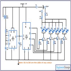
This is a very easy circuit which can be employed in automobiles as a sequential indicator light. This circuit is constructed with the help of two ICs- – a CMOS timer IC i.e. 555 timer and a decade counter IC i.e. CD4017.In this circuit astable mode of the 555 timer IC has been used to trigger the counter. Other discrete components are also used in the circuit.
At the time when power supply is provided in the circuit, voltage at pin 2 of IC1 goes down while the output pin of IC1 i.e. *(pin ?) switches to the high state. Now pin 3 of IC1 provides a positive clock pulse to pin 14 of IC2. This high pulse triggers the output pins of IC2 i.e. pin 3,2,4 and 7 high. At the same time output pin of IC2 is at low in sequence and the rate of this sequencing is proportional to the triggering frequency. Now the transistor T1, T2, T3, T4 collector starts conducting, as a result of its corresponding LEDs of this Transistor starts blinking.
S1 point in the circuit is used to select the left or right direction. So if S1 is connected with the right, all the LEDs connected on the right will blink. In the same way if S1 is connected to the Left then all the LED connected on the left will blink. Capacitor C2 in the circuit is used as a bypass capacitor.
Note- Although we have chosen yellow light for right turn and red for the right turn in this circuit., you can alter the colour of LED as per your choice.
(For demonstration purpose we have used only one LED for left turn and one for right turn.)
Components required building the circuit-
IC
IC1 NE555
IC2 CD4017
Resistor
R1 47K
VR1 500K
R3 1.2K
R4 1.2K
R5 10E
Capacitor
C1 1uF
C2 220uF
LED
D1-D8 Any colour
Transistor
T1 BC547
T2 BC547
T3 BC547
T4 BC547
Power Supply 12V
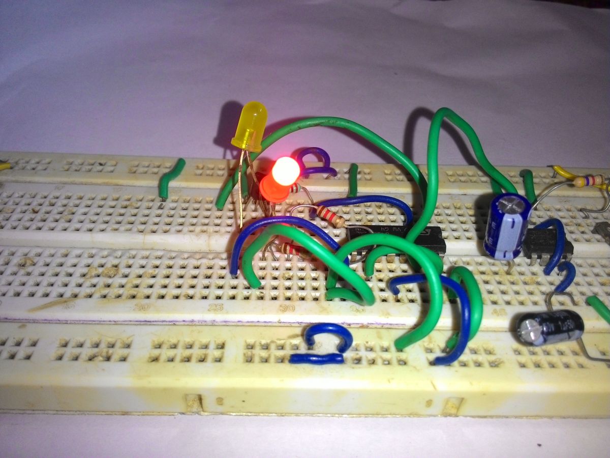
Fig. 1: Prototype of 555 IC based Car Indicator Circuit designed on a breadboard
Circuit Diagrams
Project Components
Project Video
Filed Under: Circuit Design
Filed Under: Circuit Design

Questions related to this article?
👉Ask and discuss on EDAboard.com and Electro-Tech-Online.com forums.
Tell Us What You Think!!
You must be logged in to post a comment.