Engineers Garage

  • Electronics Projects and Tutorials
    • Electronic Projects
      • Arduino Projects
      • AVR
      • Raspberry pi
      • ESP8266
      • BeagleBone
      • 8051 Microcontroller
      • ARM
      • PIC Microcontroller
      • STM32
    • Tutorials
      • Audio Electronics
      • Battery Management
      • Brainwave
      • Electric Vehicles
      • EMI/EMC/RFI
      • Hardware Filters
      • IoT tutorials
      • Power Tutorials
      • Python
      • Sensors
      • USB
      • VHDL
    • Circuit Design
    • Project Videos
    • Components
  • Articles
    • Tech Articles
    • Insight
    • Invention Stories
    • How to
    • What Is
  • News
    • Electronic Product News
    • Business News
    • Company/Start-up News
    • DIY Reviews
    • Guest Post
  • Forums
    • EDABoard.com
    • Electro-Tech-Online
    • EG Forum Archive
  • DigiKey Store
    • Cables, Wires
    • Connectors, Interconnect
    • Discrete
    • Electromechanical
    • Embedded Computers
    • Enclosures, Hardware, Office
    • Integrated Circuits (ICs)
    • Isolators
    • LED/Optoelectronics
    • Passive
    • Power, Circuit Protection
    • Programmers
    • RF, Wireless
    • Semiconductors
    • Sensors, Transducers
    • Test Products
    • Tools
  • Learn
    • eBooks/Tech Tips
    • Design Guides
    • Learning Center
    • Tech Toolboxes
    • Webinars & Digital Events
  • Resources
    • Digital Issues
    • EE Training Days
    • LEAP Awards
    • Podcasts
    • Webinars / Digital Events
    • White Papers
    • Engineering Diversity & Inclusion
    • DesignFast
  • Guest Post Guidelines
  • Advertise
  • Subscribe

Timer Operated Relay with Digital Display

By Ashutosh Bhatt August 23, 2020


The circuit presented here operates a relay for Fixed Timer Interval. So the device or machine connected with relay operates for same time. The device once switched ON, automatically switches OFF after Fixed (set) Time Interval when relay switches OFF. The Time Interval can be varied and it is displayed on 7 Segment Display. This kind of circuits can be used in many applications where it is required to operate any device or machine for Fixed Time Interval. Like

·  The Alarm Signal (or Bell) once triggered, remains ON for Fixed Time Interval and then shuts off automatically

·  In Manufacturing Industries the Motors have to be rotated for Fixed Time Interval once start button is pressed. It stops automatically when time period is over

Time operated relay circuit is build using IC555. To display the time period in seconds 2-digit decade counter is build using CD4026 chip. Another IC555 is used to provide 1 Hz pulse to update time period after every 1 sec.

Timer Operated Relay with Digital Display

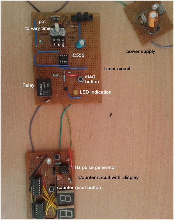
Fig. 1: Prototypes of 555 IC based Timer and Digital Counter

Circuit Description

The circuit is divided in 2 sections

1.      Timer Circuit

2.      Counter Circuit

Timer Circuit

This is the circuit (Please refer Circuit Diagram Tab) that switches ON relay for set time period. It is build using IC555. IC555 is configured in monostable mode. Its time period is determined by RC components R2 and C3. R2 is 100 K variable resistance so we can vary the time period. Minimum and maximum time period can be calculated as

Tmax = 1.1 × R2max × C3

                                                                        = 1.1 × 101 × 103 × 100 × 10-6

                                                                                                = 11 sec

And                                         Tmin = 1.1 × R2min × C3

                                                                        = 1.1 × 1000 × 100 × 10-6

                                                                                                =  0.11 sec

Note

For experiment the RC values are kept smaller to get time interval in seconds. But by choosing larger values of R and C the time interval can be set in 10s of second or in minutes also.

The output of IC555 drives three components

·             First, it drives LED2 through current limiting resistor. LED2 is used to indicate relay is ON

·        Second it drives 1 C/O (change over) relay through NPN transistor. Any load or machine or device is connected with C (common) and NO (normally open) terminals of relay

·            Third it drives reset pin of another IC555

Another IC555 is connected in astable mode. Its output frequency is determined by 100 K pot R5 and 10 uF capacitor C1. Its frequency is set to 1 Hz by varying pot R5. So LED1 blinks at every 1 sec. Output of this IC555 is given as clock pulse to counter circuit.

Counter Circuit & Circuit Operation

Counter Circuit

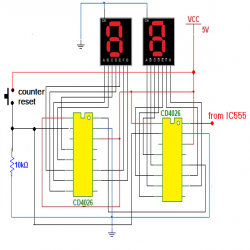
2-digit counter circuit is built using two decade counter cum display driver chips CD4026. The 1 Hz pulse output from IC555 is directly given as clock pulse input (pin 1) to 1st CD4026. (Please refer Circuit Diagram 2nd Tab)

It increment its count by 1 on every pulse input. Also it converts the count into equivalent 7-segment display code (common cathode) so that count can be displayed. It counts from 0 to 9 and again resets to 0. When it goes from 9 to 0, it generates output pulse (carry out) that can be given to next decade counter chip. So as shown in figure the carry out (pin 5) of 1st decade counter is given as clock input (pin 1) to 2nd decade counter chip. The outputs of both decade counter chips (CD4026) are, a, b, c, d, e, f, and g that can be directly given to respective inputs to common cathode type 7 segment displays. The outputs of chip CD4026 are connected to a-b-c-d-e-f-g inputs of both 7 segment displays as shown. As the count increments it is displayed on these displays from 00 to 99 and again 00. Because they are common cathode type displays, their common terminals are grounded.  To reset both chips to 0 it is required to give high pulse on reset pin (no 15). So one push button is connected to reset pins of both chips as shown, to reset counter to 00 normally both reset pins are connected to ground through 10 K resistor.

Circuit Operation

·         When supply is given, relay and LED1 (yellow) are off. Astable mustivibrator IC is also off so it does not generate 1 Hz    pulses. The counter displays 00 on seven segment. If it does not then by pressing counter reset button the it can be reset to 00

·         Set the desire time between 0.1  to 11 sec by setting pot at proper value

·         Trigger is applied to timer IC555 by pressing start push button

·         IC555 output goes high. So relay is switched ON that is indicated by yellow LED

·         At the same time the reset pin of second IC555 also becomes high

·         So it start generating 1 Hz pulses that is given to counter

·         So counter starts incrementing after every second as 0, 1, 2, ……

·         After the set time period (say 6 sec) timer IC555, its output goes low

·         So  relay is OFF, LED1 is also off and reset pin of 2nd IC555 goes low

·         So it stops generating pulses that makes counter stops counting

·         Last count is displayed on 7 segment

·         So we can observe for how much time the relay was ON

·         Again set any different time interval by changing pot value and press start button

·         The same process repeats

You may also like:


  • What are EMS/EMC immunity lab tests?

  • What are the top development boards for AI and ML?

  • What drone parts you need to build a quadcopter?

  • What’s a protective relay and what does it protect?

  • What is an Actuator Sensor Interface (AS-i)?

  • What is the LoRaWAN network and how does it work?

Circuit Diagrams

circuit1_0_0
circuit2_4

Project Components

  • The decline in Indian imports

Project Video


Filed Under: Circuit Design, Electronic Projects
Tagged With: 555 timer circuit, 7 segment display, CD 4026, IC 555, lcd, NPN Transistor
 

Next Article

← Previous Article
Next Article →

Questions related to this article?
👉Ask and discuss on Electro-Tech-Online.com and EDAboard.com forums.


Tell Us What You Think!! Cancel reply

You must be logged in to post a comment.

EE TECH TOOLBOX

“ee
Tech Toolbox: Internet of Things
Explore practical strategies for minimizing attack surfaces, managing memory efficiently, and securing firmware. Download now to ensure your IoT implementations remain secure, efficient, and future-ready.

EE Learning Center

EE Learning Center
“engineers
EXPAND YOUR KNOWLEDGE AND STAY CONNECTED
Get the latest info on technologies, tools and strategies for EE professionals.

HAVE A QUESTION?

Have a technical question about an article or other engineering questions? Check out our engineering forums EDABoard.com and Electro-Tech-Online.com where you can get those questions asked and answered by your peers!


RSS EDABOARD.com Discussions

  • MCU identification?
  • GanFet power switch starts burning after 20 sec
  • problem identifying pin purpose on PMA5-83-2WC+ amplifier
  • AC amplifier, transistor with bias network
  • modelsim not run the clock long enough

RSS Electro-Tech-Online.com Discussions

  • LED circuit for 1/6 scale diorama
  • Can I use this charger in every country?
  • Electronic board faulty?!?
  • using a RTC in SF basic
  • An Update On Tarrifs

Featured – Designing of Audio Amplifiers part 9 series

  • Basics of Audio Amplifier – 1/9
  • Designing 250 Milli Watt Audio Power Amplifier – 2/9
  • Designing 1 Watt Audio Power Amplifier – 3/9
  • Designing a Bass Boost Amplifier – 4/9
  • Designing a 6 Watt Car Audio Amplifier – 5/9
  • Design a low power amplifier for headphones- 6/9

Recent Articles

  • Fischer connector system adds ratchet locking system designed for 300g shock resistance
  • Littelfuse introduces tactile switch with enhanced bracket peg design for mounting strength
  • Infineon releases GaN switch with monolithic bidirectional design
  • Sienna Semiconductor data converters feature sample rates from 20 to 250 Msps
  • Delta’s 5,500 W power supplies achieve 97.5% energy efficiency for AI servers

EE ENGINEERING TRAINING DAYS

engineering

Submit a Guest Post

submit a guest post
Engineers Garage
  • Analog IC TIps
  • Connector Tips
  • Battery Power Tips
  • DesignFast
  • EDABoard Forums
  • EE World Online
  • Electro-Tech-Online Forums
  • EV Engineering
  • Microcontroller Tips
  • Power Electronic Tips
  • Sensor Tips
  • Test and Measurement Tips
  • 5G Technology World
  • Subscribe to our newsletter
  • About Us
  • Contact Us
  • Advertise

Copyright © 2025 WTWH Media LLC. All Rights Reserved. The material on this site may not be reproduced, distributed, transmitted, cached or otherwise used, except with the prior written permission of WTWH Media
Privacy Policy

Search Engineers Garage

  • Electronics Projects and Tutorials
    • Electronic Projects
      • Arduino Projects
      • AVR
      • Raspberry pi
      • ESP8266
      • BeagleBone
      • 8051 Microcontroller
      • ARM
      • PIC Microcontroller
      • STM32
    • Tutorials
      • Audio Electronics
      • Battery Management
      • Brainwave
      • Electric Vehicles
      • EMI/EMC/RFI
      • Hardware Filters
      • IoT tutorials
      • Power Tutorials
      • Python
      • Sensors
      • USB
      • VHDL
    • Circuit Design
    • Project Videos
    • Components
  • Articles
    • Tech Articles
    • Insight
    • Invention Stories
    • How to
    • What Is
  • News
    • Electronic Product News
    • Business News
    • Company/Start-up News
    • DIY Reviews
    • Guest Post
  • Forums
    • EDABoard.com
    • Electro-Tech-Online
    • EG Forum Archive
  • DigiKey Store
    • Cables, Wires
    • Connectors, Interconnect
    • Discrete
    • Electromechanical
    • Embedded Computers
    • Enclosures, Hardware, Office
    • Integrated Circuits (ICs)
    • Isolators
    • LED/Optoelectronics
    • Passive
    • Power, Circuit Protection
    • Programmers
    • RF, Wireless
    • Semiconductors
    • Sensors, Transducers
    • Test Products
    • Tools
  • Learn
    • eBooks/Tech Tips
    • Design Guides
    • Learning Center
    • Tech Toolboxes
    • Webinars & Digital Events
  • Resources
    • Digital Issues
    • EE Training Days
    • LEAP Awards
    • Podcasts
    • Webinars / Digital Events
    • White Papers
    • Engineering Diversity & Inclusion
    • DesignFast
  • Guest Post Guidelines
  • Advertise
  • Subscribe