Todays modern houses are equipped with many different technological facilities like
-
Automatic lights and fans
-
Remote operated curtains
-
Automatic call bell system
-
Password lock for main door
And many more such systems. An automatic gate for garage or main entrance gate of compound is one of the very popular, useful and widely used one such facility. Automatic gate means it opens automatically when any one wants to enter or exit and then it closes automatically. It is equipped with sensor that detects person/two wheeler / four wheeler (or any other object) and on detecting, it opens the gate and after few seconds the gate is automatically closed. The sensors are given on both side of gate one is inside the gate and another is outside the gate. So gate automatically open from either side when anybody wants to enter or exit.
Here the given project demonstrates the same system. It uses IR object sensor to detect any object or person, and a low RPM DC gear motor that opens and closes the gate. The project is build using AVR micro controller ATMega16. Let us see the circuit its working and operation

Fig. 1: Prototype of AVR ATMega16 based Automatic Gate controller soldered on PCBs
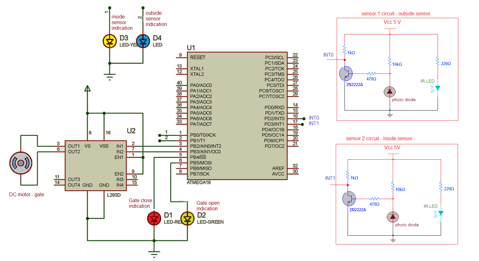
Circuit diagram:
The circuit is build using 2 identical IR object sensors, AVR micro controller ATMega16 and DC motor driver chip L293D. Few LEDs are used for different indications.
IR object Sensor :
It is build using IR LED and photo diode. The photo diode is connected in reverse biased. The IR LED and photo diode are placed align (side by side) so photo diode receives IR light not directly but reflected by any object. Its output is given to NPN transistor that is connected in switch mode. So it will just invert the output of photo diode. The final output of sensor is the collector output of transistor.
IR object sensor operation:
-
In normal condition, when there is no any object in front of sensor, the IR light does not fall on photo diode. So it does not conduct. So its output turns of the transistor and the final output of sensor is high
-
Now when any object comes in front of the sensor, the photo diode gets reflected light. It conducts and it turns on the transistor. So the transistor output – means the sensor output goes low
Output of both sensors are connected to external interrupt pins INT0 (16) and INT1(17) of ATMega16. So when any object arrives it generates an interrupt. Port B pins PB2 and PB3 drives DC motor through L293D chip. These pins are connected to inputs of L293D and the outputs of L293d are connected to motor. Two LEDs one yellow and one blue are connected to pins PB0 and PB1 that indicate which sensor has generated interrupt. Two more LEDs RED and GREEN are connected to pins PB4 and PB5 that indicates gate is open or close
Complete circuit working and operation:
-
Initially the gate is closed. The red LED is ON to indicate gate is closed
-
When any object comes in front of inside sensor (or outside sensor) it generates an interrupt. It is indicated by blue LED
-
The motor rotates CW and opens the gate. The red LED turns off and green LED turns ON
-
After the object passes through gate and comes in front of outside sensor (or inside sensor) it generates second interrupt. It is indicated by yellow LED
-
Now the motor rotates CCW and closes the gate. Again green LED turns off and red LED turns on
-
So this cycle repeats. As any one sensor generates interrupt first time the motor rotates CW and gate opens and when second sensor generates interrupt second time the motor rotates CCW and closes he gate
The program is embedded into internal ROM – FLASH of ATMega16 micro controller to perform above functionality. It’s a C program compiled in AVR studio software. Here is the complete C program.
Project Source Code
###
#include <avr/io.h>#include <avr/interrupt.h>
#include <util/delay.h>
unsigned int gate_open_flag=0; // flag to check gate is open or not
void main()
{
DDRB = 0xFF;
DDRD = 0x00;
PORTB=0x00;
MCUCR = (1<<ISC01) | (0<<ISC00) | (1<<ISC11) | (0<<ISC10);
GICR=(1<<INT0) | (1<<INT1); // enable interrupts
sei(); // enable global interrupts
while(1);
}
ISR(INT0_vect) // interrupt routine for inside
{ // sensor
PORTB = 0x01; // interrupt indication on LED
_delay_ms(200);
PORTB = 0x00;
if(gate_open_flag==1) // if gate is open
{
PORTB = 0x04; // rotate motor CCW to
_delay_ms(3000); // close it
PORTB = 0x00;
gate_open_flag=0; // clear the flag
PORTB = 0x10; // red LED on
}
else
{
PORTB = 0x08; // otherwise rotate motor CW
_delay_ms(3000); // to open gate
PORTB = 0x00;
gate_open_flag=1; // set gate open flag
PORTB = 0x20; // green LED on
}
}
ISR(INT1_vect) // interrupt routine for outside
{ // sensor
PORTB = 0x02; // same as above
_delay_ms(200);
PORTB=0x00;
if(gate_open_flag==1)
{
PORTB = 0x04;
_delay_ms(3000);
PORTB = 0x00;
gate_open_flag=0;
PORTB = 0x10;
}
else
{
PORTB = 0x08;
_delay_ms(3000);
PORTB = 0x00;
gate_open_flag=1;
PORTB = 0x20;
}
}
###
Circuit Diagrams
Project Video
Filed Under: Electronic Projects
Filed Under: Electronic Projects

Questions related to this article?
👉Ask and discuss on EDAboard.com and Electro-Tech-Online.com forums.
Tell Us What You Think!!
You must be logged in to post a comment.