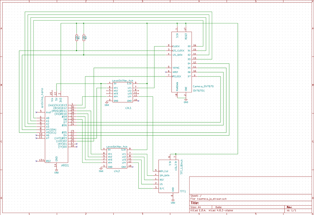
Important: Both the OV7670 camera module and 1.8 inch TFT graphic lcd are working on 3.3v power supply where as my arduino is working on 5v. So i used level shifters in my project for interfacing arduino with camera and tft. I advise you to use arduino powered on 3.3v power supply or better to used arduino nano whose 3.3v operating board is perfect for our project, this will reduce extra level shifter hardware from project.
I found a pretty neat and clean circuit on internet which i used to build my project.
You can replace level shifter ics with normal level shift resistor circuit.OV7670 Camera
|
Ov7670 camera is powered using 3.3v arduino output power. To configure the camera its registers must be assessed and written the necessary initialization commands.Registers interface is I2C. So arduino I2C module is used to configure the camera registers. Camera output is received on 8-bit data output lines. Camera data output lines are connected with arduino data pins. Ov7670 needs an extra external clock source for camera to work properly this clock is also provided by the arduino. Pclck is pin which requires an extra clock source. This clock signal is provide by arduino D12 pin which is SPI MISO(Master in slave out) pin.
|
TFT Lcd Interface
|
The 1.8 inch TFT works on SPI protocol. Arduino SPI port is used to send data to lcd. Note arduino is used in master mode and lcd in slave mode. So we are using only MOSI(Master out slave in) pin of arduino to send data to tft lcd. MISO(Master in slave out) is reserved for clock to camera. TFT is also powered using arduino 3.3v output power supply. Level shifters are also required to send data from arduino uno to tft because both are working on different voltages.
|
- LiveOV7670Library
- Adafruit_GFX_Library
One just need to make the circuit. Burn the code in arduino and its all done. Your camera will start working. For future work one can interface an SD card with arduino and can save the camera feed in SD card to view latterly as video or image. The project can be used as security camera.
Download the project code and please provide us with your feed back on the project.
Filed Under: Arduino, Microcontroller Projects


Questions related to this article?
👉Ask and discuss on EDAboard.com and Electro-Tech-Online.com forums.
Tell Us What You Think!!
You must be logged in to post a comment.