Many times when we go out of home in a hurry and forget to' on" or "off" certain appliances which sometimes creates a problem for us. Like in the morning we have to go to the office and in a rush, we sometimes forget to "off" the motor or water pump which lead to wastage of water and electricity or sometimes it happens we forget to "on" the motor which leads to scarcity of water. Hence, to solve this problem you can use this simple circuit which will "on" and "off" your electrical appliances just by using phone. You can also control other electrical appliances like your TV, refrigerator, etc. Main advantage of this cell phone based multiple device controller circuit-
1. You can control your appliances remotely from a distance just by using your telephone.
2. In this circuit, we are controlling 6 individual devices.
3. You can also control 9 individual appliances by using a single circuit. In that case you have to add one more CD4049 IC.
4. The main advantage of this circuit is single telephone at receiver side can be used to control the device and same can be used as a normal phone according to your requirement.
5. You can power the circuit from voltage range from 5V to 12V.
6. You can connect your AC operating appliances with the help of relay.
[[wysiwyg_imageupload:11687:]]
Fig. 1: Prototype of Cell Phone Based Multiple Device Controller Circuit on Breadboard
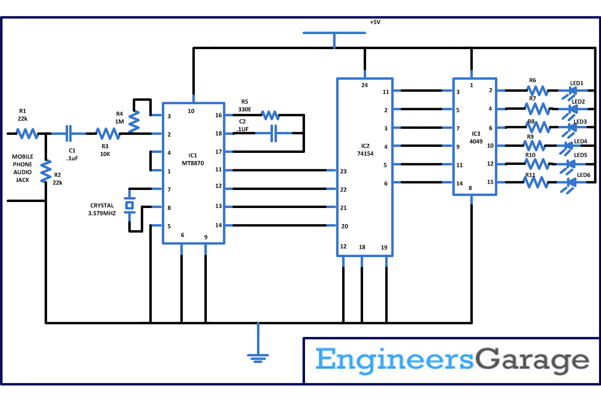
This circuit is based on 3 ICs MT8870, 74154, CD4049 with few more commonly used discrete components. Before understanding the working, let’s have a look at the working of individual IC.
1. MT8870- DTMF stands for Dual tone multiple frequencies. MT8870 is basically used in the telephone industry and various other applications. Whenever you press any button on the telephone respective tone is generated which is heard as DTMF tone. It is a DTMF to BCD converter.
2. 74154 – 74154 is a 4 line to 16 line decoder/demultiplexer. A demultiplexer is a logic circuit that takes one input signal and converts it into multiple output signals. And which output will become active depends upon the input at the control lines. In general a demultiplexer has one data input, and data output signals and m control lines with 2m = n. And multiplexer accept binary coded decimal number as input and gives you a corresponding binary number at the output.
3. CD4049 – CD4049 is a hex buffer/inverter. It is a monolithic CMOS integrated circuit constructed on P and N channel enhancement mode transistor. Works on wide voltage range vary from 3V to 15V. It can drive two TTL load at 5V over full temperature range. Important feature of CD4049 is it has special input protection which permits input voltages greater than VDD.
Working of circuit
The circuit describe here can be used to “on” and “off” six devices while dialling the number from 1 to 6 from the key pad of telephone. In this circuit DTMF signals from the telephone system is used as control signals. In this same circuit same telephone can be used for controlling the appliances and as a normal telephone for talking. So if you want to use your telephone for controlling the devices than once a call is connected dial number 0 from the keypad. Now, you can control your devices and if o is not pressed than your telephone will work like normal telephone.
Now consider a case that call has been connected and you have press 0 then IC1 that is MT8870 decodes this as 1010 binary signals that you can measure on the output pin 11,12,13,14 of IC1. Now suppose you want to “on” the first device than press 1 from the keypad of telephone. Now it will be decoded by IC1 as 0001. And the pin 11 of IC2 you will get 1010.This BCD code at the moment supply to 74154 IC. It is basically a demultiplexer whose corresponding output later than inverter IC 4049 moves to logic 1 status.And this pulse will on the LED or device connected through relay connected at the output. In the similar way you can “on” and “off” other devices.
If you want to control up to 9 devices than you have to connect a one more CD4049 IC and connect the remaining output of IC2 pin no. 7,8,9,10 to input pin of CD4049 in the similar way as connected in the circuit diagram.
Circuit Diagrams
Project Components
Project Video
Filed Under: Electronic Projects
Filed Under: Electronic Projects


Questions related to this article?
👉Ask and discuss on EDAboard.com and Electro-Tech-Online.com forums.
Tell Us What You Think!!
You must be logged in to post a comment.