(Satellite dish antenna angle controller)
What is close loop control system?
Actually, there are two types of control systems (1) open loop control system and (2) close loop control system. In the close loop control system the actual output is sensed and given as feedback along with input to the system. Instead, in open loop system the input is given to system that generates output but the output is not sensed or fed back to input. See the difference in figure given below.

Fig. 1: Block Representation of a Closed Loop Control System
In the close loop system the input is not given directly to the system. But it is given to comparator. The comparator compares the input with output feedback signal and generates error signal. This error signal is given as input to system. So, till the desire output is not generated the comparator gives error signal to drive the system and when the system generates desire output the comparator generates 0 error signal.
Thus close loop control system always generates desire output and it has always control over output. That’s why such systems are used in industrial applications, military applications, satellite applications, automobile applications, avionics application, robotics application etc. Some of the examples are
-
Avionics applications – fly by wire mechanism, auto pilot
-
Automobile applications – unmanned guided vehicle, auto car parking system
-
Robotic applications – robotic arm, path tracking robot, material handling robot
Thus one can list out numerous such applications.
The project given here demonstrates one such close loop control system. It controls the angle of dish antenna. To get maximum signal from satellite (in the space) it is require to move the dish antenna into exact angular position. So the desire angle is entered (given as input) and when the antenna rotates it actual angle is sensed continuously and given as feedback. The signal is given to rotate antenna till it reaches desire angle. When it reaches entered angle no further input is given and dish antenna stops rotating. This is how the dish antenna attains correct angular position.
The project is build using
-
AVR micro controller ATmega32
-
10 RPM DC gear motor that rotates dish antenna
-
Encoder wheel and
-
Opto interrupt sensor that senses dish antenna angle
Here are the snaps of project arrangement and set up.

Fig. 2: Prototype of Closed Loop Control System designed with Dish Antenna

Fig. 3: Prototype of AVR ATMega16 based Circuit used to control DC Motor in a Closed Loop Control System
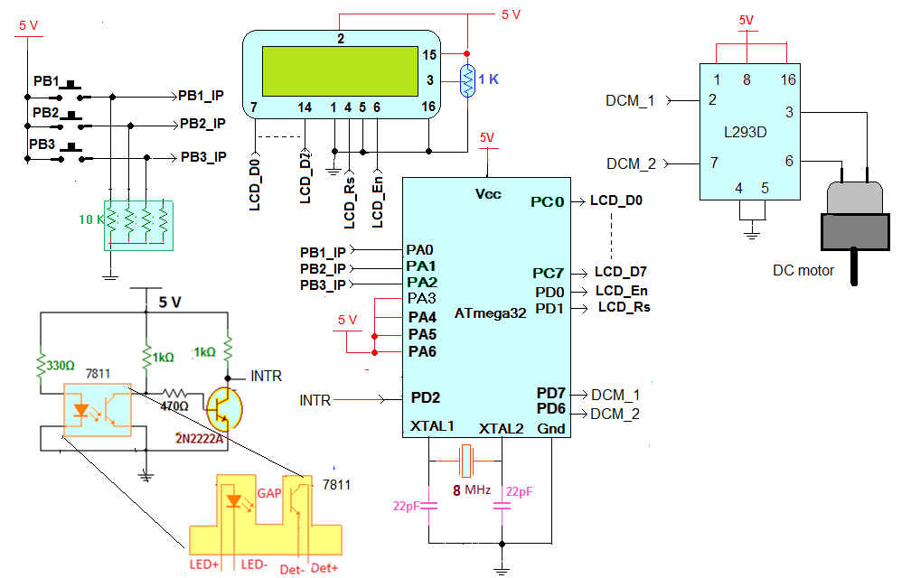
Circuit diagram:
The major building blocks are AVR micro controller ATmega32, LCD, DC motor driver chip L293D and opto interrupt sensor MOC7811.
Opto-interrupt sensor circuit:
This circuit is build around opto-interrupt sensor MOC7811. Its a combination of IR LED and photo transistor. The internal IR LED is forwarded biased to make it continuously on. current limiting resistor of 330E is used to limit the current through it.
The output of photo transistor is given as input to another NPN transistor that is connected in switch mode. The final output of sensor circuit is taken from collector of NPN transistor.
Opto-interrupt sensor circuit working and operation:
As shown in the figure there is very small gap (5 mm) in between IR LED and photo transistor so when there is no any obstacle in this gap the IR light directly falls on photo transistor. It conducts and its output goes low. Another output inverts this output and the final output of sensor circuit becomes high. But now when any obstacle enters into this gap, the IR light does not fall on photo transistor so it does not conduct. Its output goes high and through transistor inverter the final output of sensor becomes low.
In this project the encoder wheel is used that is a slotted wheel with holes at every 10o. When this wheel rotates in sensor gap the sensor output generates pulses at every 10o rotation. The encoder wheel is attached directly with the shaft of DC motor that turns dish antenna. So as the motor rotates (means the dish antenna) – the wheel rotates – the sensor generates pulses for every 10o rotation. That means the dish antenna angle position is sensed in terms of 1 pulse/10o
The output of sensor circuit is given to external interrupt pin INT0 (16) of ATMega32. Three push buttons are connected to PORTA pins PA0 – PA2 such that when button is pressed it gives logic ‘1’ input to pin. They are used to enter desire angle and rotate dish. LCD is connected to PORTC and PORTD. Its data pins are connected to PORTC and two control pins Rs and En are connected to PD0 and PD1 respectively. LCD displays desire angle and actual angle of dish antenna. Port D pins PD7 and PD6 drives DC motor through L293D chip. These pins are connected to inputs of L293D and the outputs of L293d are connected to motor.
Complete circuit working and operation:
-
Initially the dish antenna angle is set to 0o. The LCD also displays “set angle” and “dish angle” as 0o.
-
To set the angle press button 1 to increase angle by 10o. The angle can be set in between 0 – 350o by pressing button 1 and 2
-
Once desire angle is set press button 3. This will start rotating motor
-
As motor rotates, the encoder wheel also rotates so dish angle changes by every 10o that is displayed on LCD
-
The motor rotates till set angle and dish angle matches. When they matches the motor stops
-
Set angle can be increased or decreased any time in steps of 10o
-
If the set angle is increased, the motor rotates forward and if set angle is decreased it rotates reverse.
-
The LCD always shows set angle and actual dish angle
The program is embedded into internal ROM – FLASH of ATMega16 micro controller to perform above functionality. It’s a C program compiled in AVR studio software. Here is the complete C program.
Project Source Code
###
#include <avr/io.h>
#include <util/delay.h>
#include <avr/interrupt.h>
#include <string.h>
unsigned int set_angle=0, dish_angle=0,rotate_reverse_flag=0;;
void lcd_senddata(unsigned char data)
{
_delay_ms(2);
PORTD=(1<<PD0);
PORTC=data;
PORTD=(1<<PD0)|(1<<PD1);
PORTD=(1<<PD0)|(0<<PD1);
}
void lcd_sendcmd(unsigned char cmd)
{
_delay_ms(2);
PORTD=(0<<PD0);
PORTC =cmd;
PORTD=(1<<PD1);
PORTD=(0<<PD1);
}
void lcd_printstr(char *s)
{
unsigned int l,i;
l = strlen(s); // get the length of string
for(i=0;i<l;i++)
{
lcd_senddata(*s); // write every char one by one
s++;
}
}
void lcd_init()
{
lcd_sendcmd(0x3E);
lcd_sendcmd(0x0E);
lcd_sendcmd(0x01);
lcd_sendcmd(0x82);
lcd_printstr("Dish antenna");
lcd_sendcmd(0xC2);
lcd_printstr("angle control");
}
void display_value(unsigned int angle)
{
unsigned int t1,a;
unsigned char asci[3];
unsigned int t;
t = angle;
if(t>=100)
{
a=2;
while(t>=10)
{
t1=t%10;
asci[a]=t1+0x30;
t=t/10;
a--;
}
asci[0]=t+0x30;
}
else
{
t1=t%10;
asci[2]=t1+0x30;
t=t/10;
asci[1]=t+0x30;
asci[0]=0x20;
}
lcd_senddata(asci[0]);
lcd_senddata(asci[1]);
lcd_senddata(asci[2]);
lcd_senddata(0xDF);
}
void inc_angle()
{
if(set_angle<360) set_angle+=10; // increment angle by 10 deg till
lcd_sendcmd(0x8A); // 360 deg
display_value(set_angle); // display set angle
}
void dec_angle()
{
if(set_angle>0) set_angle-=10; // decrement angle by 10 deg
lcd_sendcmd(0x8A); // till 0 deg
display_value(set_angle); // display it
}
void rotate_dish()
{
if(set_angle>dish_angle) // if new set angle is more
rotate_reverse_flag=0; // than actual dish angle
else // rotate motor forward
rotate_reverse_flag=1; // otherwise rotate reverse
if(rotate_reverse_flag==0)
{ // rotate motor till set angle
while(set_angle!=dish_angle) PORTD = 0x80;// and dish angle
PORTD = 0x00; // are not same
}
else
{
while(set_angle!=dish_angle) PORTD = 0x40;// rotate reverse
PORTD = 0x00;
}
}
int main(void)
{
DDRC=0xFF; // configure ports as input and output
DDRD=0xC3;
DDRB=0xFF;
DDRA=0x00;
PORTC=0x00;
PORTD=0x04;
PORTB=0x00;
MCUCR = (1<<ISC01) | (0<<ISC00); // enable external interrupt
GICR=(1<<INT0);
sei();
lcd_init(); // initialize LCD
_delay_ms(2000); // wait for 2 set
lcd_sendcmd(0x01);
lcd_printstr("Set angle:"); // display initial set angel
display_value(set_angle);
lcd_sendcmd(0xC0);
lcd_printstr("Dish angle:"); // and dish angle
display_value(dish_angle);
loop:while(PINA==0xF8); // wait for key press
switch(PINA)
{
case 0xF5: // for push button 1
inc_angle(); // increase angle
_delay_ms(200);
break;
case 0xFA: // for push button 2
dec_angle(); // decrease angle
_delay_ms(200);
break;
case 0xFC: // for push button 3
rotate_dish(); // rotate dish
break;
}
goto loop;
}
ISR(INT0_vect) // on getting interrupt
{
if(rotate_reverse_flag==1) // if motor is rotating reverse
{
if(dish_angle>0) dish_angle-=10; // decrement dish angle
}
else
{
if(dish_angle<360) dish_angle+=10; // or increment dish angle
}
lcd_sendcmd(0xCB);
display_value(dish_angle); // display it
}
###
Circuit Diagrams
Project Video
Filed Under: Electronic Projects
Filed Under: Electronic Projects

Questions related to this article?
👉Ask and discuss on EDAboard.com and Electro-Tech-Online.com forums.
Tell Us What You Think!!
You must be logged in to post a comment.