Engineers Garage

  • Electronic Projects & Tutorials
    • Electronic Projects
      • Arduino Projects
      • AVR
      • Raspberry pi
      • ESP8266
      • BeagleBone
      • 8051 Microcontroller
      • ARM
      • PIC Microcontroller
      • STM32
    • Tutorials
      • Audio Electronics
      • Battery Management
      • Brainwave
      • Electric Vehicles
      • EMI/EMC/RFI
      • Hardware Filters
      • IoT tutorials
      • Power Tutorials
      • Python
      • Sensors
      • USB
      • VHDL
    • Circuit Design
    • Project Videos
    • Components
  • Articles
    • Tech Articles
    • Insight
    • Invention Stories
    • How to
    • What Is
  • News
    • Electronic Product News
    • Business News
    • Company/Start-up News
    • DIY Reviews
    • Guest Post
  • Forums
    • EDABoard.com
    • Electro-Tech-Online
    • EG Forum Archive
  • DigiKey Store
    • Cables, Wires
    • Connectors, Interconnect
    • Discrete
    • Electromechanical
    • Embedded Computers
    • Enclosures, Hardware, Office
    • Integrated Circuits (ICs)
    • Isolators
    • LED/Optoelectronics
    • Passive
    • Power, Circuit Protection
    • Programmers
    • RF, Wireless
    • Semiconductors
    • Sensors, Transducers
    • Test Products
    • Tools
  • Learn
    • eBooks/Tech Tips
    • Design Guides
    • Learning Center
    • Tech Toolboxes
    • Webinars & Digital Events
  • Resources
    • Digital Issues
    • EE Training Days
    • LEAP Awards
    • Podcasts
    • Webinars / Digital Events
    • White Papers
    • Engineering Diversity & Inclusion
    • DesignFast
  • Guest Post Guidelines
  • Advertise
  • Subscribe

Dc Motor Speed Control with 8051(89c51,89c52) Microcontroller using PWM Technique and l293d motor driver

By EG Projects April 16, 2019

This is a simple project/tutorial on how to control Dc motor speed using 8051(89c51,89c52) microcontroller? Dc motor or fan speed is controlled using Pwm(Pulse width Modulation) technique. Their are two ways to generate pulse width modulation signal using 8051(89c51,89c52) microcontrollers. You can generate it by using timers of 8051(89c51,89c52) microcontroller  OR you can switch a particular pin (high and low) so rapidly with some arbitrary delay in switching, that a pulse is generated as output on the pin. Best and most easy controlled way to generate PWM signal is by using internal timers of 89c51 microcontroller and in this project i am going to generate PWM using timers of 8051(89c51,89c52) microcontroller.
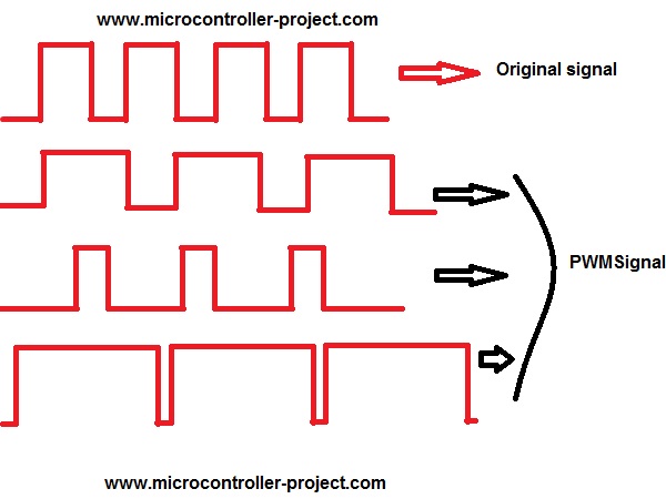
PWM in simple words changes the output voltage on a specified pin on which it is applied by varying the duty cycle of output wave form. Frequency and duty cycle of PWM signal can easily be varied using timers of 8051 microcontroller.
Figure below will clear you about PWM signals and duty cycle. Original signal duty cycle is varyied in the below diagram. 
PWM signal

PWM signal

What exactly duty cycle is?

Duty cycle is the time during which the output signal remains high for a period of wave. Period is the total time/length of a single clock wave/cycle. Hence duty cycle is time/length in a single clock cycle during which the output remains high.  
Duty Cycle

Duty Cycle

Motor speed control with 8051 microcontroller – Project requirements

  • Microcontroller 8051(89c51 or 89c52)
  • Crystal                     (11.0592MHz)
  • Capacitors   2          (33pf)
  • Push Buttons 9
  • DC Motor- Fan       (Small Toy Motor)
  • Power Supply         (5v)
  • L293D                     (DC Motor Driver)​

Picture

I am generating PWM signal of different duty cycles 00%, 10%, 20%, 50%, 80%, and 90%. 200 us is my base. For 80% duty cycle my time delay is 160 us. PWM for delays greater than 200 us are also generated 500 us, 800 us and 1000 us.    

Now how to generate these delays using 8051(89c51,89c52) microcontroller timers? Their are two timers in 89c51 microcontroller Timer-0 and Timer-1. You can use them for delay purposes or for counting an event etc. You can use these timers in Four Modes. I am using them in 16-bit mode. To learn more about timers, their modes and initialization go through the tutorial

  • 8051(89c52,89c51) Microcontrolle Timers

8051(89c52,89c51) are 8-bit microcontrollers. But you can use their timers as 16-bit. To load 16-bit value in timers you use two registers THx and TLx associated with timers. Where THx represents Timer High Byte and TLx represents Timer Low Byte (Note x is 0 or 1 depending on the timer you want to use). Here i am using Timer-0 so I will use TH0 and TL0 registers.

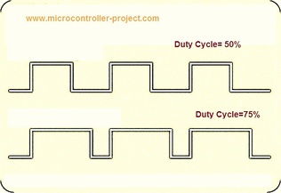
My Duty cycle base is 200 us means at 100 us duty cycle will be 50%. 50% duty cycle means both positive and negative signals are same in length(time). You can see two sine(digital) waves with duty cycles 50% and 75% in the figure at left side. Notice the difference between both waves.  

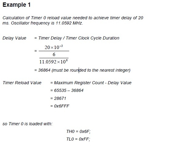
I calculated delay for 00, 20 us, 40 us, 100 us, 160 us, 180 us, 500 us, 800 us and 100 us and loaded the values obtained by the result in TH0 and TL0 registers. Formulas to calculate delay is given below with an example.


You can Calculate values of TH0 and TL0 registers for 00, 20 us, 40 us, 100 us, 160 us, 180 us, 500 us, 800 us and 100 us delays using the formula given on the right side. I calculated the values using the same formula.

PWM is generated on Port-1 pin#0. Pin#0 of Port-1 is connected to L293D. To switch between different duty cycles i used Push Buttons. Each push button corresponds to PWM of different duty cycle. Total 9 push buttons are used in the project. Eight are connected  to Port-2 and Ninth one is connected to Port-0 pin#7. Apply 5v at Pin#40&31 of Microcontroller. Ground Pin#20. Connect crystal(11.0592 MHz) to pin#18&19 of microcontroller. Connect capacitors in parallel to crystal. 

Delay Calculation for 8051(89c51,89c52) microcontroller.

Delay Calculation for 8051(89c51,89c52) microcontroller.

L293d motor driver with 89c51 microcontroller circuit diagram

Dc Motor Speed Control using 8051(89c51,89c52) microcontroller. L293d interfacing with 89c51 microcontroller.

Dc Motor Speed Control using 8051(89c51,89c52) microcontroller. L293d interfacing with 89c51 microcontroller.

L293D motor driver

Dc motors needs minimum 5 volts and 80 mA of current to work properly. 8051 microocntroller can not supply this much amount of power as output on its gpio pins. An external driver is needed to accomplish this task. L293d motor driver is best to driver small dc motors so it is made part of our project. L293d connections with 89c51 microcontroller are shown above to learn about L293d working, pin out and configuration go through the below tutorial

  • L293D Pin out and Working

In the code portion i first included the header file reg51.h. This header file must be included in every project code that is going to be compiled in keil compiler. Some single bits are initialized than. These bits represents push Buttons and Pwm output pin. In the main function first each port is initialized as input or output. 
The instruction TMOD=0x01 is initializing Timer-0 in 16-bit Mode. Do not understand take the tutorial.

  • Timer registers of 89c51 microcontroller

If-else statement is switching between different duty cycles, depending on the push button pressed. In button statements Pwm_B_20=P2^1,​ 20 represents the duty cycle corresponding to button. Like in statement Pwm_B_60=P2^4, 60 represents the 60 us high time or 30% duty cycle. Delays greater than 200 us means 100% duty cycle. 

Watch the project video Here
Sorry for the poor quality of video

Dc Motor Speed Control with 8051(89c51,89c52) microcontroller


Filed Under: 8051 Microcontroller, Electronic Projects, Microcontroller Projects


Next Article

← Previous Article
Next Article →

Questions related to this article?
👉Ask and discuss on EDAboard.com and Electro-Tech-Online.com forums.


Tell Us What You Think!! Cancel reply

You must be logged in to post a comment.

EE TECH TOOLBOX

“ee
Tech Toolbox: 5G Technology
This Tech Toolbox covers the basics of 5G technology plus a story about how engineers designed and built a prototype DSL router mostly from old cellphone parts. Download this first 5G/wired/wireless communications Tech Toolbox to learn more!

EE Learning Center

EE Learning Center
“engineers
EXPAND YOUR KNOWLEDGE AND STAY CONNECTED
Get the latest info on technologies, tools and strategies for EE professionals.

HAVE A QUESTION?

Have a technical question about an article or other engineering questions? Check out our engineering forums EDABoard.com and Electro-Tech-Online.com where you can get those questions asked and answered by your peers!


RSS EDABOARD.com Discussions

  • How best to synchronise the UCC38C45?
  • floating node warning in LTSpice
  • Collector Current Low side Has a large drop respect High Side during Miller during Double Pulse Test
  • Diode recovery test Irrm timing.
  • The Analog Gods Hate Me

RSS Electro-Tech-Online.com Discussions

  • The Analog Gods Hate Me
  • Display TFT ST7789 (OshonSoft Basic).
  • Fixing board, Easy question HEX SCHMITT
  • Can I make two inputs from one??
  • Home Smoke detectors are all Beeping Batteries are not dead.???

Featured – LoRa/LoRaWan Series

  • What is the LoRaWAN network and how does it work?
  • Understanding LoRa architecture: nodes, gateways, and servers
  • Revolutionizing RF: LoRa applications and advantages
  • How to build a LoRa gateway using Raspberry Pi
  • How LoRa enables long-range communication
  • How communication works between two LoRa end-node devices

Recent Articles

  • How to monitor temperature and humidity on a TFT display with graphics
  • Tria modules integrate edge AI processing with multi-core processors
  • pSemi introduces RF switch with 52 dBm PMAX,PEAK and 90-dBm IIP3 linearity
  • XP Power launches 1.3 kW power supply with 58.9 W/cmÂł density
  • How to enable Wi-Fi provisioning in ESP32-based IoT products

EE ENGINEERING TRAINING DAYS

engineering

Submit a Guest Post

submit a guest post
Engineers Garage
  • Analog IC TIps
  • Connector Tips
  • Battery Power Tips
  • DesignFast
  • EDABoard Forums
  • EE World Online
  • Electro-Tech-Online Forums
  • EV Engineering
  • Microcontroller Tips
  • Power Electronic Tips
  • Sensor Tips
  • Test and Measurement Tips
  • 5G Technology World
  • Subscribe to our newsletter
  • About Us
  • Contact Us
  • Advertise

Copyright © 2025 WTWH Media LLC. All Rights Reserved. The material on this site may not be reproduced, distributed, transmitted, cached or otherwise used, except with the prior written permission of WTWH Media
Privacy Policy

Search Engineers Garage

  • Electronic Projects & Tutorials
    • Electronic Projects
      • Arduino Projects
      • AVR
      • Raspberry pi
      • ESP8266
      • BeagleBone
      • 8051 Microcontroller
      • ARM
      • PIC Microcontroller
      • STM32
    • Tutorials
      • Audio Electronics
      • Battery Management
      • Brainwave
      • Electric Vehicles
      • EMI/EMC/RFI
      • Hardware Filters
      • IoT tutorials
      • Power Tutorials
      • Python
      • Sensors
      • USB
      • VHDL
    • Circuit Design
    • Project Videos
    • Components
  • Articles
    • Tech Articles
    • Insight
    • Invention Stories
    • How to
    • What Is
  • News
    • Electronic Product News
    • Business News
    • Company/Start-up News
    • DIY Reviews
    • Guest Post
  • Forums
    • EDABoard.com
    • Electro-Tech-Online
    • EG Forum Archive
  • DigiKey Store
    • Cables, Wires
    • Connectors, Interconnect
    • Discrete
    • Electromechanical
    • Embedded Computers
    • Enclosures, Hardware, Office
    • Integrated Circuits (ICs)
    • Isolators
    • LED/Optoelectronics
    • Passive
    • Power, Circuit Protection
    • Programmers
    • RF, Wireless
    • Semiconductors
    • Sensors, Transducers
    • Test Products
    • Tools
  • Learn
    • eBooks/Tech Tips
    • Design Guides
    • Learning Center
    • Tech Toolboxes
    • Webinars & Digital Events
  • Resources
    • Digital Issues
    • EE Training Days
    • LEAP Awards
    • Podcasts
    • Webinars / Digital Events
    • White Papers
    • Engineering Diversity & Inclusion
    • DesignFast
  • Guest Post Guidelines
  • Advertise
  • Subscribe