Engineers Garage

  • Electronic Projects & Tutorials
    • Electronic Projects
      • Arduino Projects
      • AVR
      • Raspberry pi
      • ESP8266
      • BeagleBone
      • 8051 Microcontroller
      • ARM
      • PIC Microcontroller
      • STM32
    • Tutorials
      • Audio Electronics
      • Battery Management
      • Brainwave
      • Electric Vehicles
      • EMI/EMC/RFI
      • Hardware Filters
      • IoT tutorials
      • Power Tutorials
      • Python
      • Sensors
      • USB
      • VHDL
    • Circuit Design
    • Project Videos
    • Components
  • Articles
    • Tech Articles
    • Insight
    • Invention Stories
    • How to
    • What Is
  • News
    • Electronic Product News
    • Business News
    • Company/Start-up News
    • DIY Reviews
    • Guest Post
  • Forums
    • EDABoard.com
    • Electro-Tech-Online
    • EG Forum Archive
  • DigiKey Store
    • Cables, Wires
    • Connectors, Interconnect
    • Discrete
    • Electromechanical
    • Embedded Computers
    • Enclosures, Hardware, Office
    • Integrated Circuits (ICs)
    • Isolators
    • LED/Optoelectronics
    • Passive
    • Power, Circuit Protection
    • Programmers
    • RF, Wireless
    • Semiconductors
    • Sensors, Transducers
    • Test Products
    • Tools
  • Learn
    • eBooks/Tech Tips
    • Design Guides
    • Learning Center
    • Tech Toolboxes
    • Webinars & Digital Events
  • Resources
    • Digital Issues
    • EE Training Days
    • LEAP Awards
    • Podcasts
    • Webinars / Digital Events
    • White Papers
    • Engineering Diversity & Inclusion
    • DesignFast
  • Guest Post Guidelines
  • Advertise
  • Subscribe

DC Motor Speed Testing Using Arduino

By Ashutosh Bhatt January 17, 2017

In DC motor speed testing, the PWM is applied to the motor and its duty cycle is varied from min to max. While applying PWM the actual RPM of DC motor is also measured and note down to see how motor speed (RPM) varies as PWM width varies. Along with this, the applied voltage to the motor is also measured to see the motor speed at different applied voltage. Finally, after noting down all the values, the observation table is prepared for pulse width (duty cycle), applied voltage and motor speed in RPM. This table is used to prepare duty cycle->RPM graph or applied voltage->RPM graph of the motor.

The given project demonstrates above example. It applies PWM to DC motor to vary its speed from min to max and max to min continuously and also measures following parameters.

1) PWM width in %

2) Applied voltage to motor

3) Motor speed in RPM

It uses arduino UNO board to generate PWM and measure/calculate above 3 parameters. These parameters are displayed on 16×4 LCD. It is very easy to vary the speed of DC motor using arduino. Arduino can generate PWM on its analog output pin and when it is applied to DC motor, its speed varies. So it is very simple and easy task. To measure RPM, opto-interrupt sensor MOC7811 is used. When motor completes 1 revolution, the sensor generates 1 pulse and such pulses are calculated by arduino to calculate RPM. So let us see how this is done. Let’s start with circuit diagram first, followed by its descriptions and operation.

CIRCUIT DESCRIPTION

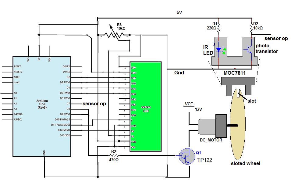
As shown in the figure, the circuit is built using arduino UNO development board, 16×4 LCD, NPN Darlington transistor TIP122 and opto interrupt sensor MOC7811.

• The analog output pin 9 of arduino drives 12V@2000 RPM DC motor through TIP122. This pin is given to the base input of TIP122 through current limiting resistor R2 and DC motor is connected to the collector of TIP122.

• The internal IR LED of MOC7811 is given forward bias using 5V supply from the arduino board through current limiting resistor R1. Internal photo transistor is pulled up by resistor R4. The collector output of the transistor is connected to digital pin 7 or arduino.

•  LCD data pins D4 to D7 are connected to digital pins 5, 4, 3 and 2 of arduino while control pins Rs and En are connected to 12 and 11. RW pin is connected to ground. Vcc pin and LED+ pin are connected to 5 V supply from arduino board and Vss pin and LED- pins are connected to arduino board ground.

•  One pot is connected to Vee pin to vary contras of LCD.

Here is the snap of arrangement.

Prototype of Arduino based DC Motor Speed Controller

Fig. 1: Prototype of Arduino based DC Motor Speed Controller

CIRCUIT OPERATION

•  First, the motor is given 12 V supply through an external power supply. Next, the arduino board, LCD, and the sensor are given supply through USB from PC / laptop.

•  Initially, the LCD shows different parameters as “PWM ip: PWM Duty: PWM volt: speed:”

•  Then arduino starts applying PWM to motor with maximum pulse width.

•  So motor will start rotating at maximum speed. Sometimes a delay is provided to allow the motor to attain full speed.

•  As the motor starts rotating, the slotted wheel attached to its shaft will also rotate.

• The MOC7811 sensor is placed such a way that the slot of wheel passes through sensor air gap. Thus when the motor rotates one full revolution, the slot passes through sensor gap. Due to the slot in the wheel, the IR light falls on phototransistor. So transistor conducts and generates a negative pulse in collector output. Thus each rotation of motor produces a pulse.

•  The frequency of these pulses is actually RPS (- revolution per second) of the motor. To measure the frequency of this pulse first the ON time is measured then OFF time is measured and from this frequency is calculated as -:

Time period = Ton + Toff (in us)

Frequency = 1000000/time period

• This frequency is the speed of the motor in RPS. From this RPS, the speed of the motor is calculated in RPM as -:

RPM = 60×RPS

• The PWM input is varied from 250 to 100 in step of 15. That is directly displayed on LCD.

• The ON time and OFF time of PWM output are also measured to calculate the PWM duty cycle as -:

PWM duty = [PWM_Ton / (PWM_Ton + PWM_Toff)] × 100

•  Finally, voltage applied to the motor is calculate as -:

Voltage applied to motor = motor voltage × duty

= (12/100) × duty

•  First, the PWM input is decreased from 250 to 100 in 10 steps of 15 and then again it is increased from 100 to 250 and this cycle is repeated continuously.

•  So motor speed continuously decreases and then continuously increases. We can observe the change in motor speed that is displayed on LCD as speed in RPM.

Thus the given project varies the speed of DC motor and also measures it accurately. It displays % of pulse width applied to motor along with applied voltage. So one can note down motor speed in RPM at different voltage and pulse width in observation table for further needs.

Project Source Code

###


#include <LiquidCrystal.h>


LiquidCrystal lcd(12, 11, 5, 4, 3, 2);

#define pwm_ip 8

#define rps_ip 7

int ontime,offtime,duty,pw=255,rps,rpm;

float volt,period;

long int rps_Ton,rps_Toff,rps_time;   

void setup()

{

  pinMode(pwm_ip,INPUT);

  pinMode(rps_ip,INPUT);

  lcd.begin(16, 4);

  lcd.clear();

  lcd.print("PWM_ip:255");

  lcd.setCursor(0,1);

  lcd.print("PWM_duty:100%");

  lcd.setCursor(0,2);

  lcd.print("PWM_volt:12.00");  

  lcd.setCursor(0,3);

  lcd.print("speed:");  

}

void loop()

{

   for(pw=250;pw>100;pw-=15) // decrease the pulse width by 2%

     {

        analogWrite(9,pw); // generate PWM

        delay(7000); // apply delay for motor to attain full speed

        ontime = pulseIn(pwm_ip,HIGH); // measure ON time of PWM 

        offtime = pulseIn(pwm_ip,LOW);    // measure OFF time of PWM

        period = ontime+offtime;    // calculate total PWM time

        duty = (ontime/period)*100; // calculate % pulse width 

        volt = 0.12*duty;  // calculate applied motor voltage

        rps_Ton = pulseIn(rps_ip,HIGH); // calculate ON time of RPS pulse input

        rps_Toff = pulseIn(rps_ip,LOW);  // calculate OFF time or RPS pulse

        rps_time = rps_Ton+rps_Toff; // calculate total time

        rps = 1000000/rps_time;   // calculate frequency that is RPS

        rpm = 60*rps;   // calculate RPM from RPS

        lcd.setCursor(7,0); // display all the values

        lcd.print(pw);

        lcd.setCursor(9,1); 

        lcd.print(duty);

        lcd.print('%');    

        lcd.setCursor(9,2);

        lcd.print(volt); 

        lcd.print('v'); 

        lcd.setCursor(6,3);

        lcd.print(rpm); 

        lcd.print(" RPM");         

     }  

    for(pw=100;pw<250;pw+=15) // increase the pulse width and 

     {

        analogWrite(9,pw); // do same as above

        delay(7000);

        ontime = pulseIn(pulse_ip,HIGH);

        offtime = pulseIn(pulse_ip,LOW);   

        period = ontime+offtime;   

        duty = (ontime/period)*100; 

        volt = 0.12*duty; 

        rps_Ton = pulseIn(rps_ip,HIGH);

        rps_Toff = pulseIn(rps_ip,LOW); 

        rps_time = rps_Ton+rps_Toff;

        rps = 1000000/rps_time;  

        rpm = 60*rps;  

        lcd.setCursor(7,0);

        lcd.print(pw);

        lcd.setCursor(9,1); 

        lcd.print(duty);

        lcd.print('%');    

        lcd.setCursor(9,2);

        lcd.print(volt); 

        lcd.print('v'); 

        lcd.setCursor(6,3);

        lcd.print(rpm); 

        lcd.print(" RPM");        

     }   

}

###


Circuit Diagrams

Circuit-Diagram-Arduino-Based-DC-Motor-Speed-Controller_0

Project Video


Filed Under: Electronic Projects


Next Article

← Previous Article
Next Article →

Questions related to this article?
👉Ask and discuss on Electro-Tech-Online.com and EDAboard.com forums.


Tell Us What You Think!! Cancel reply

You must be logged in to post a comment.

EE TECH TOOLBOX

“ee
Tech Toolbox: 5G Technology
This Tech Toolbox covers the basics of 5G technology plus a story about how engineers designed and built a prototype DSL router mostly from old cellphone parts. Download this first 5G/wired/wireless communications Tech Toolbox to learn more!

EE Learning Center

EE Learning Center
“engineers
EXPAND YOUR KNOWLEDGE AND STAY CONNECTED
Get the latest info on technologies, tools and strategies for EE professionals.

HAVE A QUESTION?

Have a technical question about an article or other engineering questions? Check out our engineering forums EDABoard.com and Electro-Tech-Online.com where you can get those questions asked and answered by your peers!


RSS EDABOARD.com Discussions

  • is there vay for credit card size phone charger?
  • Innovus Scan Reorder deletes Scan In Pad
  • How to get 3D model of ACPL-847-300E
  • How to find the resonance frequency and impedance of a planar spiral coil in HFSS?
  • Why so few Phase shift full bridge controllers?

RSS Electro-Tech-Online.com Discussions

  • Can I make two inputs from one??
  • The Analog Gods Hate Me
  • How to make string LEDs?
  • Fixing board, Easy question HEX SCHMITT
  • It's Amazing What A Buck And A Quarter....

Featured – LoRa/LoRaWan Series

  • What is the LoRaWAN network and how does it work?
  • Understanding LoRa architecture: nodes, gateways, and servers
  • Revolutionizing RF: LoRa applications and advantages
  • How to build a LoRa gateway using Raspberry Pi
  • How LoRa enables long-range communication
  • How communication works between two LoRa end-node devices

Recent Articles

  • How to monitor temperature and humidity on a TFT display with graphics
  • Tria modules integrate edge AI processing with multi-core processors
  • pSemi introduces RF switch with 52 dBm PMAX,PEAK and 90-dBm IIP3 linearity
  • XP Power launches 1.3 kW power supply with 58.9 W/cm³ density
  • How to enable Wi-Fi provisioning in ESP32-based IoT products

EE ENGINEERING TRAINING DAYS

engineering

Submit a Guest Post

submit a guest post
Engineers Garage
  • Analog IC TIps
  • Connector Tips
  • Battery Power Tips
  • DesignFast
  • EDABoard Forums
  • EE World Online
  • Electro-Tech-Online Forums
  • EV Engineering
  • Microcontroller Tips
  • Power Electronic Tips
  • Sensor Tips
  • Test and Measurement Tips
  • 5G Technology World
  • Subscribe to our newsletter
  • About Us
  • Contact Us
  • Advertise

Copyright © 2025 WTWH Media LLC. All Rights Reserved. The material on this site may not be reproduced, distributed, transmitted, cached or otherwise used, except with the prior written permission of WTWH Media
Privacy Policy

Search Engineers Garage

  • Electronic Projects & Tutorials
    • Electronic Projects
      • Arduino Projects
      • AVR
      • Raspberry pi
      • ESP8266
      • BeagleBone
      • 8051 Microcontroller
      • ARM
      • PIC Microcontroller
      • STM32
    • Tutorials
      • Audio Electronics
      • Battery Management
      • Brainwave
      • Electric Vehicles
      • EMI/EMC/RFI
      • Hardware Filters
      • IoT tutorials
      • Power Tutorials
      • Python
      • Sensors
      • USB
      • VHDL
    • Circuit Design
    • Project Videos
    • Components
  • Articles
    • Tech Articles
    • Insight
    • Invention Stories
    • How to
    • What Is
  • News
    • Electronic Product News
    • Business News
    • Company/Start-up News
    • DIY Reviews
    • Guest Post
  • Forums
    • EDABoard.com
    • Electro-Tech-Online
    • EG Forum Archive
  • DigiKey Store
    • Cables, Wires
    • Connectors, Interconnect
    • Discrete
    • Electromechanical
    • Embedded Computers
    • Enclosures, Hardware, Office
    • Integrated Circuits (ICs)
    • Isolators
    • LED/Optoelectronics
    • Passive
    • Power, Circuit Protection
    • Programmers
    • RF, Wireless
    • Semiconductors
    • Sensors, Transducers
    • Test Products
    • Tools
  • Learn
    • eBooks/Tech Tips
    • Design Guides
    • Learning Center
    • Tech Toolboxes
    • Webinars & Digital Events
  • Resources
    • Digital Issues
    • EE Training Days
    • LEAP Awards
    • Podcasts
    • Webinars / Digital Events
    • White Papers
    • Engineering Diversity & Inclusion
    • DesignFast
  • Guest Post Guidelines
  • Advertise
  • Subscribe