Engineers Garage

  • Electronic Projects & Tutorials
    • Electronic Projects
      • Arduino Projects
      • AVR
      • Raspberry pi
      • ESP8266
      • BeagleBone
      • 8051 Microcontroller
      • ARM
      • PIC Microcontroller
      • STM32
    • Tutorials
      • Sensor Series
      • 3D Printing
      • AI
      • ARDUINO Compatible Coding
      • Audio Electronics
      • Battery Management
      • Beginners Electronics Series
      • Brainwave
      • Digital electronics (DE)
      • Electric Vehicles
      • EMI/EMC/RFI
      • EVs
      • Hardware Filters
      • IoT tutorials
      • LoRa/LoRaWAN
      • Power Tutorials
      • Protocol
      • Python
      • RPI Python Programming
      • Sensors
      • USB
      • Thermal management
      • Verilog
      • VHDL
    • Circuit Design
    • Project Videos
    • Components
  • Articles
    • Tech Articles
    • Insight
    • Invention Stories
    • How to
    • What Is
  • News
    • Electronic Product News
    • Business News
    • Company/Start-up News
    • DIY Reviews
    • Guest Post
  • Forums
    • EDABoard.com
    • Electro-Tech-Online
    • EG Forum Archive
  • DigiKey Store
    • Cables, Wires
    • Connectors, Interconnect
    • Discrete
    • Electromechanical
    • Embedded Computers
    • Enclosures, Hardware, Office
    • Integrated Circuits (ICs)
    • Isolators
    • LED/Optoelectronics
    • Passive
    • Power, Circuit Protection
    • Programmers
    • RF, Wireless
    • Semiconductors
    • Sensors, Transducers
    • Test Products
    • Tools
  • Learn
    • eBooks/Tech Tips
    • Design Guides
    • Learning Center
    • Tech Toolboxes
    • Webinars & Digital Events
  • Resources
    • Digital Issues
    • EE Training Days
    • LEAP Awards
    • Podcasts
    • Webinars / Digital Events
    • White Papers
    • Engineering Diversity & Inclusion
  • Guest Post Guidelines
  • Advertise
  • Subscribe

Displaying ASCII Characters on 16×2 Character lcd Using Microchip PIC16f877 Microcontroller

By EG Projects August 24, 2019

In this tutorial i am going to print/display ASCII characters on 16×2 lcd using pic16f877 microcontroller. Lcd is interfaced with pic microcontroller in 8-bit mode. Code is written in c language. High tech c compiler is used to compile code and code is written in Mp-lab ide. Interfacing 16×2 lcd with pic microcontroller and displaying characters on lcd is very easy. Only the portion which is little bit complex is how to generate/display ASCII characters on lcd. Well you don’t need to generate ASCII characters they are already present in the 16×2 lcd controller (HD44780) Ram, like other characters and numbers. You just need to know how to invoke the ASCII characters to be displayed on the lcd screen. 

Project Requirements

  • Microchip Pic16f877 microcontroller.
  • 16×2 character lcd. 
  • Crystal 20MHz
  • Power Supply
  • Bread board or Design PCB(Printed circuit board)
  • Potentiometer/Variable resistor (For setting lcd contrast)
If you are new in the field of microcontrollers and lcd’s and don’t know about lcd pin out, working and internal structure of lcd then please go through the following tutorials. They will clear you about the working of 16×2 lcd. You will learn how to display characters on lcd? Difference between commands and data send to lcd?  It will also explain you about how to use lcd in 4-bit and 8-bit mode. 

16×2 lcd Pin out and Working

How to display data to 16×2 lcd?

Difference b/w lcd in 4-bit and 8-bit mode?

The circuit diagram of the project is given below. Port-B of Pic16f877 microcontroller is connected with data pins of 16×2 lcd. It means Port-B is used to send commands and data to 16×2 lcd. Lcd control signals(read/write, enable, register select) are provided using individual bits of Port-D. All the other connections are normal connections applying +5 volts to microcontroller and lcd. You can see the circuit diagram given below. Rs(Register select) is connected to Port-D Pin#6. En(Enable) is connected to Port-D Pin#7. Read/Write pin is grounded. Lcd will always remain in write state since we made the R/W pin ground. 

16x2 lcd interfaced in 8-bit mode with pic microcontroller

16×2 lcd interfaced in 8-bit mode with pic microcontroller

Project Code

Coming to the code portion, I first include the header file htc.h. If you are using high tech c compiler always include this library, this library is necessary to be included in every project that is going to be compiled with high tech c compiler. It contains the compilers directives etc. Then the frequency of the oscillator is defined which is 20 MHz. Then individual pins of Port-D are defined. These pins are used to provide control signals to lcd. delay() function is used to generate some arbitrary delay where necessary. lcdcmd() function is sending commands to lcd with control signals. display() function is sending data to lcd with control signals. lcdint() function is initializing our lcd(8-bit mode, display on ,cursor off etc). 

Important Instruction

In the main function two instructions are invoking ascii characters. The instruction i=j/10; where j is integer(int) and i is character(char). Now when we divide two integers and save result in character(char) variable. The result is stored in ascii format. Since j is 0 and dividing 0 by 10 gives 0. So i contains 0, ASCII value of zero.
The ascii character 0 is present at address 0x30. To go to address 0x00 negate 0x30 from 0x30. The instruction i=i-0x30; is doing the same job. First i contains 0x30 after executing i=i-0x30 i contains 0x00. Hence we are at starting address of ascii characters. Now increment the address one by one and display the ascii character associated with that address on the lcd screen.  

HD44780 ASCII characters addresses

HD44780 ASCII characters addresses
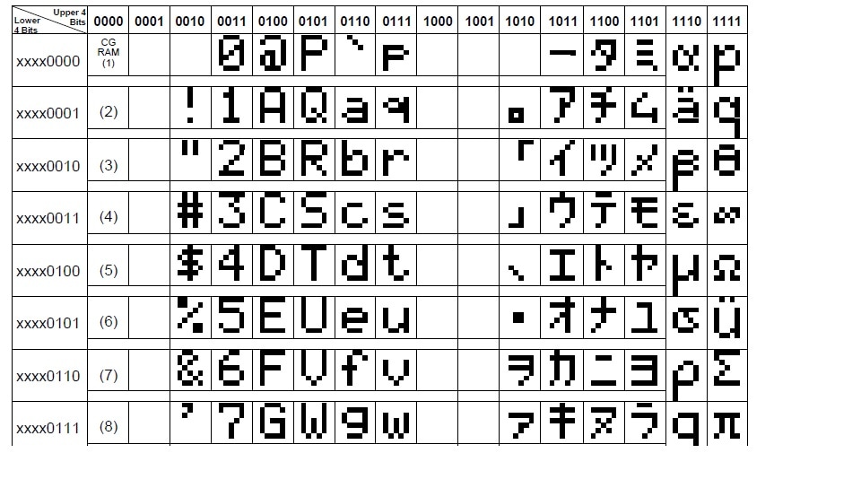
Note that the ascii characters of the HD44780 controller differs from the standard ascii characters. The HD44780 controller contains ascii characters in the format given on the right side. Some addresses are also void. So don’t get confused when you see the characters like below displayed on your lcd screen.
Total digits in ram of 16×2 lcd are 256. So i decided to display them all. It contains ASCII, numeric, alphabet and special characters(Chinese). Some address are void so nothing will display on the lcd screen across these addresses.   
Download the project files , code and simulation. The code is written in c language using Mp-lab software and high tech c compiler. The simulation is made in proteaus 8.0. Please give us your feed back on the project.
Project Code/Files

Filed Under: Electronic Projects, PIC Microcontroller


Next Article

← Previous Article
Next Article →

Questions related to this article?
👉Ask and discuss on EDAboard.com and Electro-Tech-Online.com forums.


Tell Us What You Think!! Cancel reply

You must be logged in to post a comment.

Submit a Guest Post

submit a guest post

EE TECH TOOLBOX

“ee
Tech Toolbox: Power Efficiency
Discover proven strategies for power conversion, wide bandgap devices, and motor control — balancing performance, cost, and sustainability across industrial, automotive, and IoT systems.

EE Learning Center

EE Learning Center
“engineers
EXPAND YOUR KNOWLEDGE AND STAY CONNECTED
Get the latest info on technologies, tools and strategies for EE professionals.

HAVE A QUESTION?

Have a technical question about an article or other engineering questions? Check out our engineering forums EDABoard.com and Electro-Tech-Online.com where you can get those questions asked and answered by your peers!


RSS EDABOARD.com Discussions.

  • Can anyone please help me with this single board computer?
  • Anyone successfully communicated to the BlueNRG-M0 module on the B-L4S5I-IOT01A board
  • How to Build an Audio Tone Control?
  • Current version of LTspice not working on Windows 11?
  • Addressable Latch in My Logic Project

RSS Electro-Tech-Online.com Discussions

  • KiCad custom symbol definition correct approach
  • Measuring controller current output with a meter
  • restarting this Christmas project
  • Anyone In The US Ordered From AliExpress Recently?
  • My Advanced Realistic Humanoid Robots Project

Featured Tutorials

Real Time Hardware Filter Design

  • Practical implementation of bandpass and band reject filters
    Practical implementation of bandpass and band reject filters
  • Practical application of hardware filters with real-life examples
    Practical application of hardware filters with real-life examples
  • A filter design example
    A filter design example
  • Types of filter responses
    Types of filter responses
  • What are the two types of hardware filters?
    What are the two types of hardware filters?
  • What are hardware filters and their types?
    What are hardware filters and their types?
More Tutorials >

Recent Articles

  • Posifa sensors improve low-flow accuracy in compact systems
  • Acopian releases low-profile power supplies rated to 900 W
  • Octavo Systems OSDZU-3 REF Development Platform
  • Same Sky adds enclosure design to its audio engineering capabilities
  • Waterproof SMA-to-MHF I LK assemblies introduced by Amphenol RF

EE ENGINEERING TRAINING DAYS

engineering
Engineers Garage
  • Analog IC TIps
  • Connector Tips
  • Battery Power Tips
  • EDABoard Forums
  • EE World Online
  • Electro-Tech-Online Forums
  • EV Engineering
  • Microcontroller Tips
  • Power Electronic Tips
  • Sensor Tips
  • Test and Measurement Tips
  • 5G Technology World
  • Subscribe to our newsletter
  • About Us
  • Contact Us
  • Advertise

Copyright © 2025 WTWH Media LLC. All Rights Reserved. The material on this site may not be reproduced, distributed, transmitted, cached or otherwise used, except with the prior written permission of WTWH Media
Privacy Policy

Search Engineers Garage

  • Electronic Projects & Tutorials
    • Electronic Projects
      • Arduino Projects
      • AVR
      • Raspberry pi
      • ESP8266
      • BeagleBone
      • 8051 Microcontroller
      • ARM
      • PIC Microcontroller
      • STM32
    • Tutorials
      • Sensor Series
      • 3D Printing
      • AI
      • ARDUINO Compatible Coding
      • Audio Electronics
      • Battery Management
      • Beginners Electronics Series
      • Brainwave
      • Digital electronics (DE)
      • Electric Vehicles
      • EMI/EMC/RFI
      • EVs
      • Hardware Filters
      • IoT tutorials
      • LoRa/LoRaWAN
      • Power Tutorials
      • Protocol
      • Python
      • RPI Python Programming
      • Sensors
      • USB
      • Thermal management
      • Verilog
      • VHDL
    • Circuit Design
    • Project Videos
    • Components
  • Articles
    • Tech Articles
    • Insight
    • Invention Stories
    • How to
    • What Is
  • News
    • Electronic Product News
    • Business News
    • Company/Start-up News
    • DIY Reviews
    • Guest Post
  • Forums
    • EDABoard.com
    • Electro-Tech-Online
    • EG Forum Archive
  • DigiKey Store
    • Cables, Wires
    • Connectors, Interconnect
    • Discrete
    • Electromechanical
    • Embedded Computers
    • Enclosures, Hardware, Office
    • Integrated Circuits (ICs)
    • Isolators
    • LED/Optoelectronics
    • Passive
    • Power, Circuit Protection
    • Programmers
    • RF, Wireless
    • Semiconductors
    • Sensors, Transducers
    • Test Products
    • Tools
  • Learn
    • eBooks/Tech Tips
    • Design Guides
    • Learning Center
    • Tech Toolboxes
    • Webinars & Digital Events
  • Resources
    • Digital Issues
    • EE Training Days
    • LEAP Awards
    • Podcasts
    • Webinars / Digital Events
    • White Papers
    • Engineering Diversity & Inclusion
  • Guest Post Guidelines
  • Advertise
  • Subscribe