Engineers Garage

  • Electronic Projects & Tutorials
    • Electronic Projects
      • Arduino Projects
      • AVR
      • Raspberry pi
      • ESP8266
      • BeagleBone
      • 8051 Microcontroller
      • ARM
      • PIC Microcontroller
      • STM32
    • Tutorials
      • Sensor Series
      • Engineering Deep Dives
      • AI
      • ARDUINO Compatible Coding
      • Audio Electronics
      • Battery Management
      • Beginners Electronics Series
      • Brainwave
      • Digital electronics (DE)
      • Electric Vehicles
      • EMI/EMC/RFI
      • EVs
      • Hardware Filters
      • IoT tutorials
      • LoRa/LoRaWAN
      • Power Tutorials
      • Protocol
      • Python
      • RPI Python Programming
      • Sensors
      • USB
      • Thermal management
      • Verilog
      • VHDL
    • Circuit Design
    • Project Videos
    • Components
  • Articles
    • Tech Articles
    • Insight
    • Invention Stories
    • How to
    • What Is
  • News
    • Electronic Product News
    • Business News
    • Company/Start-up News
    • DIY Reviews
    • Guest Post
  • Forums
    • EDABoard.com
    • Electro-Tech-Online
    • EG Forum Archive
  • DigiKey Store
    • Cables, Wires
    • Connectors, Interconnect
    • Discrete
    • Electromechanical
    • Embedded Computers
    • Enclosures, Hardware, Office
    • Integrated Circuits (ICs)
    • Isolators
    • LED/Optoelectronics
    • Passive
    • Power, Circuit Protection
    • Programmers
    • RF, Wireless
    • Semiconductors
    • Sensors, Transducers
    • Test Products
    • Tools
  • Learn
    • eBooks/Tech Tips
    • Design Guides
    • Learning Center
    • Tech Toolboxes
    • Webinars & Digital Events
  • Resources
    • Digital Issues
    • EE Training Days
    • LEAP Awards
    • Podcasts
    • Webinars / Digital Events
    • White Papers
    • Engineering Diversity & Inclusion
  • Guest Post Guidelines
  • Advertise
  • Subscribe

DIY: Distortion Pedal

By Ashutosh Bhatt June 13, 2020


Ever wondered how those crunch sounds come from the guitars of modern day Rock gods. Well, the answer to this is electronics. So let us go through the history of this “rock” sound. When electric guitars were invented, amplifiers in those days were tube amplifier which unlike today’s amplifiers used triodes or tube valve instead of transistors to amplify signal. The amplifiers in those days were big and bulk. And when they were played at full volume, they produce a “distorted” sound because the guitar signal got too amplified and hence clipped. The great guitarist Jimi Hendrix was the first guitarist to recognise that guitar and the amplifier together can be used as an instrument and started using this distorted sound to produce music. Thus rock music was invented.

But tube amplifiers were unreliable, consumed lot of power and were expensive. Thus electronic engineers started to develop circuits which produced the same effect as a fully driven tube amp but were a lot smaller, effective and reliable. This gave birth to distortion pedals with transistors.


Ever wondered how those crunch sounds come from the guitars of modern-day Rock gods? Well, the answer to this is electronics. So let us go through the history of this “rock” sound. When electric guitars were invented, amplifiers in those days were tube amplifier which unlike today’s amplifiers used triodes or tube valve instead of transistors to amplify signal. The amplifiers in those days were big and bulky. And when they were played at full volume, they produce a “distorted” sound because the guitar signal got too amplified and hence clipped. The great guitarist Jimi Hendrix was the first guitarist to recognise that guitar and the amplifier together can be used as an instrument and started using this distorted sound to produce music. Thus rock music was invented.

But tube amplifiers were unreliable, consumed lot of power and were expensive. Thus electronic engineers started to develop circuits which produced the same effect as a fully driven tube amp but were a lot smaller, effective and reliable. This gave birth to distortion pedals with transistors.

Implemented Circuit

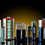
Fig. 1: Prototype of Distortion Pedal

Distortion pedals general have three stages. First stage is a buffer stage, which prevent loss of signal due to impedance mismatch between the previous stage and the pedal. This can be a simple common collector transistor. The next stage is the amplification stage where guitar signal is amplified.  This is usually done using common source transistors or op amps. The third stage is the clipping stage which emulates the clipping of a fully driven tube amp. Clipping is done using diodes or mosfets. The final stage of course is tone control and output buffer stage which controls the frequencies of the output signal and helps to prevent signal loss.

Depending on what kind of electronic circuits are used inside a pedal, distortion pedal are of many kinds. For example, a distortion pedal for a bass guitar and electric guitar will have different tone control circuit as bass guitar will operate at lower frequencies as compared to an electric guitar. Also different diodes will give different clipping and hence different tone to the guitar signal.

Circuit Description

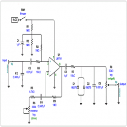
The schematic of a simple guitar distortion pedal is given in the circuit diagram tab. This circuit uses an opamp instead of a transistor for amplification. As opamps have very high input impedance, there is no need for a dedicated input buffer. Capacitor C2 is used as a low pass filter to shunt high frequencies to ground and hence cuts high frequency noise. C3 is used for low frequency roll off. R5 in conjunction with C4 allow the gain and roll off point to be adjusted and along with the diodes etc. determine the “Character” of the pedal. C4 is very important in setting the “Character” of the distortion.  Halving it raises the roll off point to 1440Hz, decreases gain and makes it more Distortion like IMHO.  Doubling it lowers the roll off point to 360Hz increases gain and makes if more Fuzz. Hence it decides the tone of the pedal. R5 – sets max gain when Drive is at minimum resistance/max gain.  In conjunction with C4 it sets the low freq roll off point for the op amp gain. This acts as two stage distortion.  At first the diodes will clip and when the drive is high enough, the op amp will start clipping as well. 

R1,R2 and R3 are used to bias the incoming signal and R3 helps improve the input impedance. R6 is reverse log potentionmeter. This changes the gain of the gain of the opamp and hence makes the output signal more muddier. R8 is a log potentiometer which controls the volume of the pedal. It acts as a voltage divider, more the wiper is away from the more the volume.

It is advisable to keep the circuit inside a metal container as it will reduce the interference from the surrounding. The capacitors values can be tweaked to change the roll of frquencies of the circuit and henc change the tone of the pedal. Some popular distortion pedals include Boss DD-1, Ibanez Tube Screamer and Big Pi Muff. Also a bypass circuit must be used otherwise the signal chain will be broken if the pedal is switched off.

Analog pedals are very expensive and hence they are getting replaced by digital equivalent which uses digital signal processing to produce the same effect. These digital units have Digital Signal Processor which run DSP algoritms to emulates analog effects. They are cheaper and can work as a replacement for multiple pedals and hence are popular.

I building it with your hands will cost you less than $10 whereas buying it will cost upwards of $150.

So if you have interest in DIY projects then go make this and keep rocking!!.


You may also like:


  • What are the top development boards for AI and ML?

  • What types of motors are used in electric vehicles?

  • What is Wireless Electric Vehicle Charging System (WEVCS)?
  • battery selection low power design
    What are the battery-selection criteria for low-power design?

  • Home Automation : An Overview

  • Electric Cars : Structure

Circuit Diagrams

image-2_0

Project Components

  • The decline in Indian imports


Filed Under: Electronic Projects
Tagged With: distortion, pedal
 

Next Article

← Previous Article
Next Article →

Questions related to this article?
👉Ask and discuss on Electro-Tech-Online.com and EDAboard.com forums.


Tell Us What You Think!! Cancel reply

Log in to leave a comment:

Lost your password?

Don't have an account? Register here

Submit a Guest Post

submit a guest post

EE TECH TOOLBOX

“ee
Tech Toolbox: Sensors
In this Tech Toolbox, we cover some of those technologies driving the next generation of connected systems, including ultra-low-power sensing strategies that extend node battery life, and 60 GHz CMOS radar for contactless health and presence detection.

EE Learning Center

EE Learning Center
“engineers
EXPAND YOUR KNOWLEDGE AND STAY CONNECTED
Get the latest info on technologies, tools and strategies for EE professionals.

HAVE A QUESTION?

Have a technical question about an article or other engineering questions? Check out our engineering forums EDABoard.com and Electro-Tech-Online.com where you can get those questions asked and answered by your peers!


RSS EDABOARD.com Discussions.

  • Resonance problem of transmission line with sector bias circuit passing through wall
  • Is a 10:1 DC inverter 40kW possible?
  • Enhancing Boost Converter Efficiency: From Practical Limitations to a Series-Boost Differential Topology
  • strategy to deside which material is the best for RF board
  • Which Graphics Card Should I Buy for My Dream Gaming PC?

RSS Electro-Tech-Online.com Discussions

  • How charging is done in Transformer Inverters
  • Transistor K2 X T5
  • using Swordfish but the matrix fails
  • Boss Chromatic Tuner TU-3
  • Mystery amp noise - ??

Featured Tutorials

Learn - VHDL Tutorials (22 Part)

  • VHDL Tutorial – 11: Designing half and full-subtractor circuits
    VHDL Tutorial – 11: Designing half and full-subtractor circuits
  • VHDL Tutorial – 12: Design a 8-bit parity generator and circuit checker
    VHDL Tutorial – 12: Design a 8-bit parity generator and circuit checker
  • VHDL tutorial 13: Design 3×8 decoder and 8×3 encoder using VHDL
    VHDL tutorial 13: Design 3×8 decoder and 8×3 encoder using VHDL
  • VHDL Tutorial 14: Design 1×8  demultiplexer and 8×1 multiplexer using VHDL
    VHDL Tutorial 14: Design 1×8  demultiplexer and 8×1 multiplexer using VHDL
  • VHDL Tutorial 17: Design a JK flip-flop (with preset and clear) using VHDL
    VHDL Tutorial 17: Design a JK flip-flop (with preset and clear) using VHDL
  • VHDL Tutorial 18: Design a T flip-flop (with enable and an active high reset input) using VHDL
    VHDL Tutorial 18: Design a T flip-flop (with enable and an active high reset input) using VHDL
More Tutorials >

Recent Articles

  • Amphenol RF launches 40 GHz solderless connectors
  • STMicroelectronics adds 200g vibration sensor for factories
  • Smarter HVAC Climate Solutions by TE
  • Amphenol RF adds NEX10 jack for 1.37 mm cable
  • Samtec headers support 2 to 50 pins

EE ENGINEERING TRAINING DAYS

engineering
Engineers Garage
  • Analog IC TIps
  • Connector Tips
  • Battery Power Tips
  • EDABoard Forums
  • EE World Online
  • Electro-Tech-Online Forums
  • EV Engineering
  • Microcontroller Tips
  • Power Electronic Tips
  • Sensor Tips
  • Test and Measurement Tips
  • 5G Technology World
  • Subscribe to our newsletter
  • About Us
  • Contact Us
  • Advertise

Copyright © 2026 WTWH Media LLC. All Rights Reserved. The material on this site may not be reproduced, distributed, transmitted, cached or otherwise used, except with the prior written permission of WTWH Media
Privacy Policy

Search Engineers Garage

  • Electronic Projects & Tutorials
    • Electronic Projects
      • Arduino Projects
      • AVR
      • Raspberry pi
      • ESP8266
      • BeagleBone
      • 8051 Microcontroller
      • ARM
      • PIC Microcontroller
      • STM32
    • Tutorials
      • Sensor Series
      • Engineering Deep Dives
      • AI
      • ARDUINO Compatible Coding
      • Audio Electronics
      • Battery Management
      • Beginners Electronics Series
      • Brainwave
      • Digital electronics (DE)
      • Electric Vehicles
      • EMI/EMC/RFI
      • EVs
      • Hardware Filters
      • IoT tutorials
      • LoRa/LoRaWAN
      • Power Tutorials
      • Protocol
      • Python
      • RPI Python Programming
      • Sensors
      • USB
      • Thermal management
      • Verilog
      • VHDL
    • Circuit Design
    • Project Videos
    • Components
  • Articles
    • Tech Articles
    • Insight
    • Invention Stories
    • How to
    • What Is
  • News
    • Electronic Product News
    • Business News
    • Company/Start-up News
    • DIY Reviews
    • Guest Post
  • Forums
    • EDABoard.com
    • Electro-Tech-Online
    • EG Forum Archive
  • DigiKey Store
    • Cables, Wires
    • Connectors, Interconnect
    • Discrete
    • Electromechanical
    • Embedded Computers
    • Enclosures, Hardware, Office
    • Integrated Circuits (ICs)
    • Isolators
    • LED/Optoelectronics
    • Passive
    • Power, Circuit Protection
    • Programmers
    • RF, Wireless
    • Semiconductors
    • Sensors, Transducers
    • Test Products
    • Tools
  • Learn
    • eBooks/Tech Tips
    • Design Guides
    • Learning Center
    • Tech Toolboxes
    • Webinars & Digital Events
  • Resources
    • Digital Issues
    • EE Training Days
    • LEAP Awards
    • Podcasts
    • Webinars / Digital Events
    • White Papers
    • Engineering Diversity & Inclusion
  • Guest Post Guidelines
  • Advertise
  • Subscribe