The circuit presented here generates different colours from 3 LEDs – RED, GREEN and BLUE only using AVR micro controller ATMega32.
As we all know there are three primary colours – red, green and blue. All other colours can be made by mixing these three colours in different amount. The picture tube of any television set also uses this principle. Today’s modern LCD and LED TVs are also based on the same principle. They generate millions of different colours by setting different levels of red, green and blue colour and generates realistic like picture.
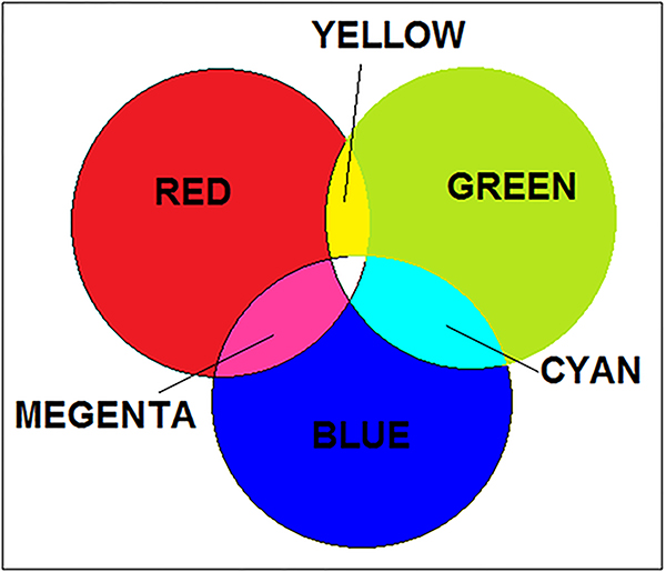
From these three primary colours, secondary colours yellow, cyan and magenta are generated by adding two these three colours as given below
RED + GREEN = YELLOW
GREEN + BLUE = CYAN
RED + BLUE = MAGENTA
The following figure shows the colour chart for primary and secondary colours

Fig. 1: Image showing Primary Colors
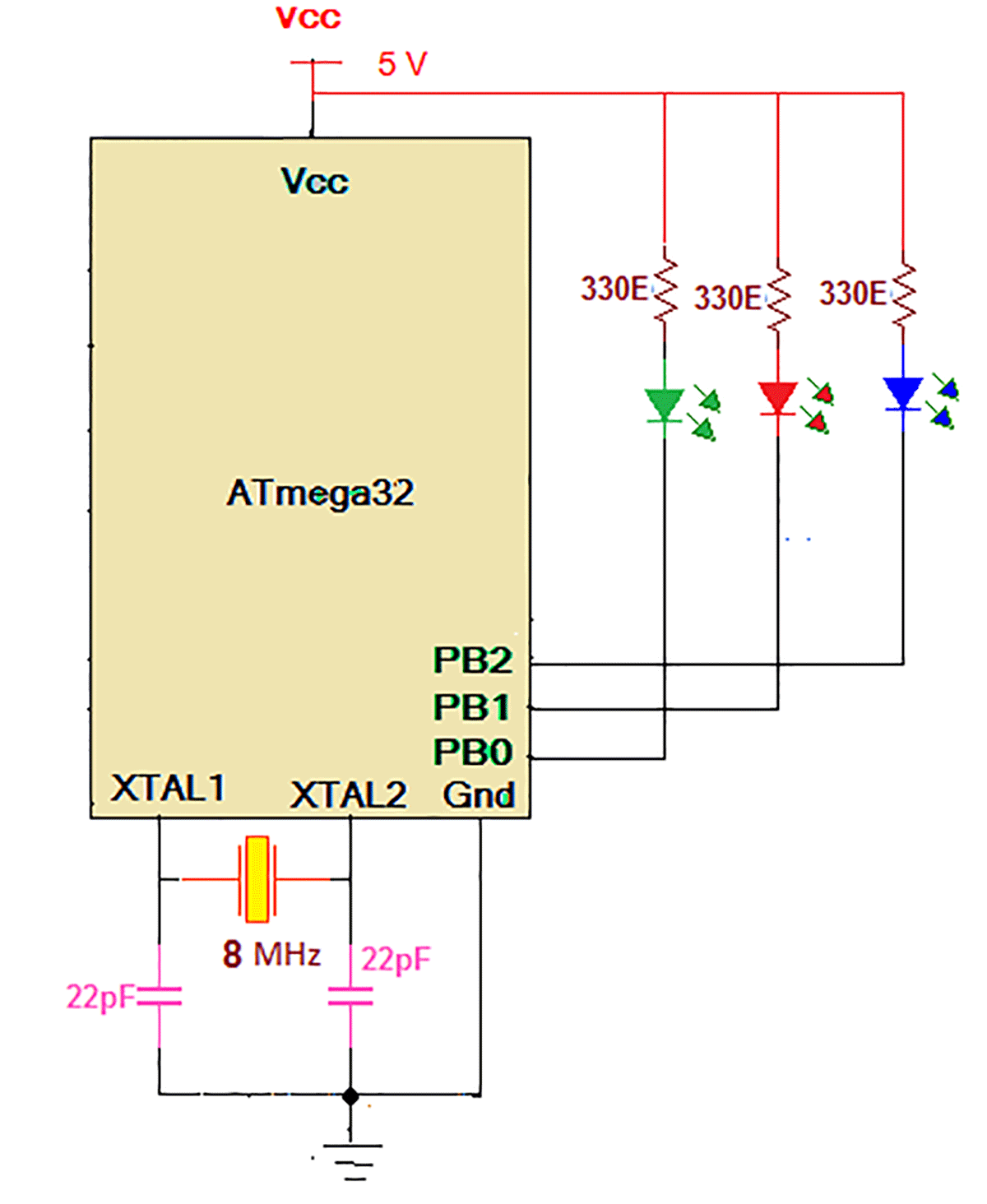
The given circuit demonstrates how to generates these three primary and three secondary colours from three RED, GREEN, BLUE colour LEDs with the help of AVR micro controller
Circuit description:
(Check the circuit diagram tab for complete circuit for how to generate different colours from RED-GREEN-BLUE LEDs using AVR micro controller)
As shown in figure, the circuit is made up of 3 LEDs of red, green and blue colour, AVR micro controller ATmega32 and 8 MHz crystal
Three LEDs BLUE, RED and GREEN are connected with PORTB pins PB2, PB1 and PB0 respectively with 330Ω current limiting resistors as shown. All three LEDs are connected in sinking current configuration. One 8 MHz crystal along with two 22 pf capacitors is connected to crystal input pins XTAL1 and XTAL2. It gives basic clock internal operation and program execution.
Circuit operation:
The anodes of LEDs are connected to Vcc and cathodes are connected to PORTB pins. So to turn LED ON, low logic (0) has to be given to respective pin.
To generate three primary colours RED, GREEN and BLUE, the respective LED is turned ON by making particular port pin low. To generate secondary colours, at a time any two LEDs are turned ON by making two pins low simultaneously. Please refer the table given below

Fig. 2: Table showing bit values at output port for color generation on RGB LED
So to generate different colours, LEDs are turned ON by sending data to PORTB as per given in table. The data bytes are given to PORTB one by one with 2 second delay in between. The program is loaded into internal FLASH of ATmega32 to perform above functionality. Click on the tab to see the C program written and compiled in AVR studio software.
Project Source Code
###
#include <avr/io.h>
#include <util/delay.h>
int main()
{
DDRB = 0x07; // declare PORTB pins as output
PORTB= 0x07; // set all pins to high to turn off all LEDs
while(1) // continue loop
{
PORTB = 0xFE; // GREEN LED ON
_delay_ms(2000); // 2 second delay
PORTB = 0xFD; // RED LED ON
_delay_ms(2000);
PORTB = 0xFB; // BLUE LED ON
_delay_ms(2000);
PORTB = 0xFC; // RED n GREEN ON => YELLOW
_delay_ms(2000);
PORTB = 0xF9; // RED n BLUE ON => MAGENTA
_delay_ms(2000);
PORTB = 0xFA; // BLUE n GREEN ON => CYAN
_delay_ms(2000);
}
}###
Circuit Diagrams
Filed Under: Electronic Projects


Questions related to this article?
👉Ask and discuss on Electro-Tech-Online.com and EDAboard.com forums.
Tell Us What You Think!!
You must be logged in to post a comment.