This is a project based on Arduino board which can measure the unknown resistance values and perform diode test and continuity testing. When we connect the unknown resistor on the breadboard circuit, the 16×2 LCD displays the resistor value and when we connect a diode the LCD displays the type of diode if it is a good one. When we take the probes out from the breadboard and connect it across a continuous path, the meter indicates the continuity by blinking an LED. The project uses an Arduino pro mini board whose ADC feature is used along with the concept of Voltage Divider circuit to develop this Ohmmeter.

Fig. 1: Prototype of Arduino based Digital Ohmmeter

Fig. 2: Image of Arduino based Digital Ohmmeter showing measured resistance
Architecture of the project
The entire project can be divided into three basic blocks;
1) Resistance/Diode/Continuity Sensor Unit
2) Processor Unit
3) Display Unit

Fig. 3: Block Diagram of Arduino based Digital Ohmmeter
The Sensor Unit takes three inputs, Unknown resistor, Diode and a Continuous path to be detected. When the unknown resistor is connected as input, the output voltage varies between 0 and 5V proportional to the value of resistance. When the unknown diode is connected as input, the output voltage will be 4.3V for Silicon diode and 4.7V for Germanium diode. When a continuous path is connected as input, the output voltage will be 5V.
The Processor Unit takes input voltage in the range of 0 to 5V. This unit calculates the resistance value, detects the diode type and continuous path from the input voltage value. The unit then sendsa 4bit data to the Display Unit which includes the resistance value or diode type. The Processor Unit also glows an LED if it detect a continuous path.
The Display Unit takes the 4bit data from the Processor Unit and produces a 16*2 display for the resistance value, diode type.
Resistance/Diode/Continuity Sensor Unit
A basic voltage divider circuit is used as the Resistance/Diode/Continuity Sensing Unit to provide an output, which is the voltage equivalent of the unknown resistor, diode or continuous path connected as the input. From this output voltage we can calculate the value of unknown resistance, detect the diode type or detect a continuous path.
Voltage divider:
Voltage divider is a basic electronic circuit consists of number of resistors connected in series, where the total input voltage gets distributed across the resistors. The fraction of input voltage that drops across a particular resistor depends on the value of that resistance.

Fig. 4: Circuit Diagram of a Voltage Divider Network used in sensing analog voltage
In the above voltage divider circuit used in this project, the input voltage ‘V’ is distributed across the resistors R1 and R2 as voltages V1 and V2 respectively.
V1 = V / (R1 + R2) * R1
V2 = V / (R1 + R2) * R2
Or
R1 = R2 * ((V / V2) – 1)
R2 = R1 / ((V / V2) – 1)
Let us assume if R1 is the unknown resistance, since we know the values of input voltage V that we are applying and we can measure the voltage V2, then we can calculate the value of R1 if we know the value of R2.
Design the value of R2 in circuit:
The following equation helps in selecting the value for R2;
R2 = R1 / ((V / V2) – 1)
Let us choose the maximum value for R1 to be measured as 1M ohms. We know that we are applying 5V as ‘V’ and ‘V2’ should be at least 4.88 mV, which is the ‘ADC Voltage Resolution’ in this particular project. ADC Voltage Resolution is the minimum voltage that the ADC in the Processor Unit can detect.
Applying these values to the above equation we get the value of R2 as follows;
R2 = 10^6 / ((5 / 4.88 * 10^-3) – 1) = 976 ohms, use 1K standard resistor.
Unknown resistor as input:
Assume if R1 is the unknown resistance, and we know the values of V = 5V and R2 = 1000, now we can calculate the value of R1 after measuring the voltage V2.

Fig. 5: Circuit Diagram of a Voltage Divider Network used in Arduino based Ohmmeter
R1 = 1000 * ((5 / V2) – 1)
Unknown Diode as input:
The test diode will be connected as R1. Whenever a diode operates in forward direction, the voltage across it will be 0.7V for silicon and 0.3V for germanium diode. Hence for a supply voltage V = 5V, the V1 will be 0.7 V and V2 will be 4.3 V for silicon diode and for germanium diode V1 will be 0.3 V and V2 will be 4.7 V.

Fig. 6: Circuit Diagram of Voltage Divider network with one resistor replaced by a diode
Continuous path as input:
Here the R1 will be 0 ohms for a continuous path and the entire supply voltage V = 5V appears across V2.

Fig. 7: Circuit Diagram of equivalent Voltage Divider network with diode replaced by continuous path
Requirement for Range selector in circuit:
We require multiple ranges in an ohmmeter due to the error appears in readings because of Resistance Tolerance. All standard resistors specify a percentage of error from their expected value which is called Resistance Tolerance. The Tolerance can be read from the color code. In this project we have used resistors whose tolerance is ±5%.
a) Decrease in the ratio of R1/R2 decreases the error:
Consider the value of R1 = 1K and it is measured with different values of R2. Using the equation
V2 = V / (R1 + R2) * R2 to calculate the value of V2 with tolerance and without tolerance;
R2 = 100K, R1/R2 = 0.01
Tolerance = 0%, R2 = 100K:
V2mintol = (5 * 101000) / 100000 = 4.950 V
Tolerance = +5%, R2 = 105K:
V2maxtol = (5 * 106000) / 105000 = 4.952 V
Error Factor = V2maxtol – V2mintol= 0.002 V
R2 = 10K, R1/R2 = 0.1
Tolerance = 0%, R2 = 10K:
V2mintol = (5 * 10000) / 11000 = 4.545 V
Tolerance = +5%, R2 = 10.5K:
V2maxtol = (5 * 10500) / 11500 = 4.565 V
Error Factor = V2maxtol – V2mintol= 0.02 V
From the above two examples, we can see that as the ratio of R1/R2 increases, the error in V2 also increase or as the ratio of R1/R2 decreases, the error in V2 also decreases.
b) There is a limit beyond which the R1/R2 cannot decrease further:
Consider the equation for calculating the R1,
R1 = R2 * ((V / V2) – 1)
To get a non-zero resistance value for R1, (V / V2) should be greater than 1. If V = 5V, V2 should be less than 5V, and hence the maximum value of
V2 = 5 – VRESOLUTION
V2 = 5 – 0.00488 = 4.995
Applying in the above equation;
R1 = R2 * ((5/4.995) – 1)
Or R1 / R2 = 0.001
Hence the smallest ratio of R1/R2 is 0.001.
Hence to measure different values of R1 with minimum error we need different set of R2. R1 whose value need to be measured is connected with an R2 which gives the least ratio of R1/R2, and that ratio should be greater than 0.001.

Fig. 8: Circuit Diagram showing different R2 resistances tested for getting full range of Ohmmeter
Processor Unit
The processor unit in this project is the Arduino board and it uses the ADC module to read the output voltage from the Sensor Unit. In the Arduino board we are using an 8 channel, 10 bit ADC with the reference voltage pin connected to 5 V. The ADC reads the voltage V2 and generates an equivalent value ‘ValueADC‘at the ADC register.
The voltage output from the Sensor Unit V2 is calculated using the following equation;
V2 = ValueADC * VRESOLUTION
Where;
VRESOLUTION is the ‘ADC Voltage Resolution’ or the minimum voltage that the ADC can detect for a given reference voltage and given output bit.
The ‘ADC Voltage Resolution’ which is the minimum voltage that the ADC can detect, is dependent on the ‘Resolution of the ADC’ which is the number of bits in the ADC output register.
Calculating the ADC Voltage Resolution:
For a specified ‘Resolution of the ADC’, and for anapplied reference voltage, we calculate the ‘ADC Voltage Resolution’ as follows;
VRESOLUTION = (VREFRENCE / 2RESOLUTION)
Where;
VREFRENCE is the voltage to which the reference pin of the ADC is connected
RESOLUTION is the specified Resolution of the ADC
Calculating for a ‘VREFRENCE’ of 5V and ‘RESOLUTION’ of 10 bits, we get the value
VRESOLUTION = 5V / 1024 = 4.88 milli Volts
Now the voltage output from the Sensor Unit V2 is calculated
V2 = ValueADC * 4.88, milli Volts

Fig. 9: Overview of ADC channels built-in Arduino Uno
The following section of the code reads the ADC channel A1 to obtain the average voltage of V2.
voltage_average_value = 0;
for(sample_count = 0; sample_count< 10; sample_count ++)
{
adc_value = analogRead(A1);
voltage_average_value = voltage_average_value + adc_value;
delay(10);
}
voltage_average_value = voltage_average_value / 10;
voltage_average_value = voltage_average_value * 0.00488;
Resistance measuring:
For a reference voltage of 5V and for a resolution of 10 bits, we use the following equation to calculate the Output voltage ‘V2’ from the Sensor Unit
V2 = ValueADC * 4.88, milli Volts
The code running in the Arduinoobtains the ‘ValueADC’, which then used to calculate the voltage ‘V2’ with the help of previously discussed equation;
V2 = ValueADC * 4.88, milli Volts
Once ‘V2’ is obtained the value of unknown resistance value ‘R1’ is calculated using the known values of ‘R2’, ‘V2’ and ‘V’ with the help of previously discussed equation;
R1 = R2 * ((V / V2) – 1)
The following section of code measures the resistance with R2 = 1000 ohms, and display on LCD;
resistance = (1000 * (5 – voltage_average_value)) / voltage_average_value;
if (resistance > 10000)
{
lcd.print(resistance / 1000);
lcd.print(” KE”);
}
else
{
lcd.print(resistance);
lcd.print(” E”);
}
Continuous path detecting:
When the R1 is 0, the entire 5V appears across the resistor R2 which the ADC detects and the LCD indicates that a continuous path is detected.
Diode testing:
Whenever the ADC detects a 4.3 volt as V2, it displays on the LCD that a Silicon diode has been detected and is working good, similarly whenever the ADC detects a 4.7 volt as V2, it displays on LCD that a Germanium diode has been detected and is working good.
The following piece of code detects the type of diode and displays;
if ((resistance > 145) && (resistance < 165))
{
lcd.clear();
lcd.setCursor(0, 0);
lcd.print(“Diode “);
lcd.print(“Silicon”);
}
else if ((resistance > 60) && (resistance < 80))
{
lcd.clear();
lcd.setCursor(0, 0);
lcd.print(“Diode “);
lcd.print(“Germanium”);
}
else;
Display Unit
The display unit in this project uses a common 16*2 LCD on which the Arduino displays the resistor value and diode type. The LCD has been wired in four bit mode to reduce the number of output pins of the Arduino board to be used.

Fig. 10: Image of Character LCD showing measured resistance
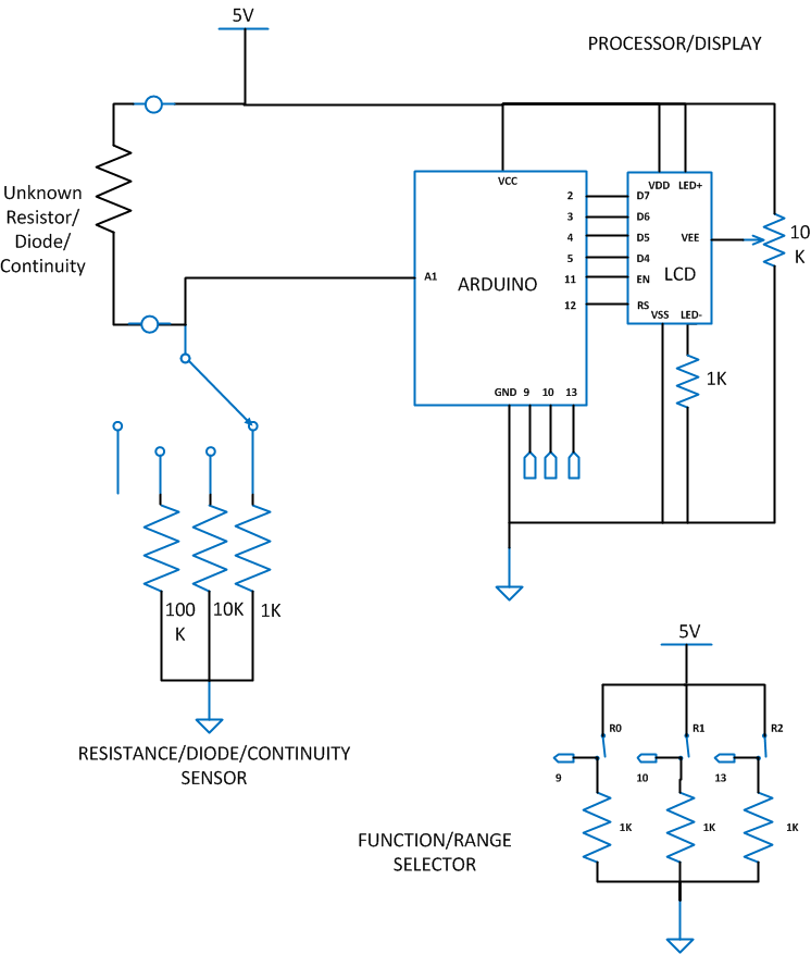
Circuit Diagram
The complete circuit diagram of the Arduino based Ohmmeter is given in which the unknown resistor, diode or continuous path is connected in Voltage Divider circuit whose ‘R2’ value can be selected using a range selector switch.
The resistance ranges and the diode testing function can be selected using the Function/Range selector switch as shown in the following table; Value 1 indicates switch closed, and value 0 indicates switch open.
|
R0 |
R1 |
RANGE |
|
0 |
1 |
10K |
|
1 |
0 |
50K |
|
1 |
1 |
500K |
|
R2 |
FUNCTION |
|
0 |
RESISTANCE / CONTINUITY |
|
1 |
DIODE TEST |
Microcontroller Code
The code identifies whether to perform resistance check or diode check by reading the values of Function/Range selector switch. The code continuously read the ADC register to calculate the value of the unknown resistance. Each time a resistance value is obtained, the code compares the value with different ranges to identify whether it is a Silicon diode, Germanium diode or pure resistor. Whenever a resistance is found in between the range of 60 to 80 (when V2 = 4.7V), the code displays the message that “Germanium diode OK”. Similarly when a resistance is found in between the range of 145 to 165 (when V2 = 4.3V), the code displays the message that “Silicon diode OK”. When the resistance value is found to be fewer than 10, then it displays “Continuous path”.
The code running in the Arduino used the library function analogRead() to obtain the ADC value and lcd.print() to display the data on 16*2 LCD.

Fig. 11: Flow Chart of Arduino Code used for measurement of resistance
Project Source Code
###
#include <LiquidCrystal.h>
LiquidCrystal lcd(12, 11, 5, 4, 3, 2);
#define resistance_R50 100000
#define resistance_R500 1000000
#define resistance_V2 10000
#define caliberation_V2 1.1
#define range50_mul (resistance_R50 / resistance_V2) * caliberation_V2
#define range500_mul (resistance_R500 / resistance_V2) * caliberation_V2
#define resistance_Ri 10
#define resistance_Cr 100000
#define resistance_Rb 100000
#define resistance_Re 10
#define resistance_R2 1000
int adc_value = 0;
int voltage_peak_value = 0;
int discharge_voltage_V0 = 0;
int discharge_voltage_V1 = 0;
float voltage_average_value = 0;
float dc_voltage_V0 = 0;
float ac_voltage_V0 = 0;
float dc_voltage_V1 = 0;
float dc_voltage_V2 = 0;
float ac_voltage_V1 = 0;
float dc_current_I0 = 0;
float dc_current_I1 = 0;
float ac_current_I0 = 0;
float dc_power = 0;
float ac_power = 0;
float npn_pnp_hfe = 0;
float capacitance = 0;
unsigned long resistance;
unsigned long sample_count = 0;
unsigned long discharge_time_T0 = 0;
unsigned long discharge_time_T1 = 0;
char fn0 = 6;
char fn1 = 7;
char fn2 = 8;
char rn0 = 9;
char rn1 = 10;
char rn2 = 13;
char function_select [4];
char range_select [4];
void setup()
{
lcd.begin(16, 2);
lcd.print(" EG LABS ");
delay(3000);
pinMode(fn0, INPUT);
pinMode(fn1, INPUT);
pinMode(fn2, INPUT);
pinMode(rn0, INPUT);
pinMode(rn1, INPUT);
pinMode(rn2, INPUT);
}
void loop()
{
function_select [0] = digitalRead(fn0) + '0';
function_select [1] = digitalRead(fn1) + '0';
function_select [2] = digitalRead(fn2) + '0';
function_select [3] = '�';
range_select [0] = digitalRead(rn0) + '0';
range_select [1] = digitalRead(rn1) + '0';
range_select [2] = digitalRead(rn2) + '0';
range_select [3] = '�';
//============================= RESISTANCE ========================================//
voltage_average_value = 0;
for(sample_count = 0; sample_count < 10; sample_count ++)
{
adc_value = analogRead(A1);
voltage_average_value = voltage_average_value + adc_value;
delay(10);
}
voltage_average_value = voltage_average_value / 10;
voltage_average_value = voltage_average_value * 0.00488;
if (range_select [2] == '0')
{
lcd.clear();
lcd.setCursor(0, 0);
if ( 0 == strncmp (range_select, "01", 2) )
lcd.print("0-10K: ");
else if ( 0 == strncmp (range_select, "10", 2) )
lcd.print("10-100K: ");
else if ( 0 == strncmp (range_select, "11", 2) )
lcd.print("100K-1M: ");
if (voltage_average_value > 0)
{
if ( 0 == strncmp (range_select, "01", 2) )
resistance = (1000 * (5 - voltage_average_value)) / voltage_average_value;
else if ( 0 == strncmp (range_select, "10", 2) )
resistance = (10000 * (5 - voltage_average_value)) / voltage_average_value;
else if ( 0 == strncmp (range_select, "11", 2) )
resistance = (100000 * (5 - voltage_average_value)) / voltage_average_value;
else;
if (resistance > 10000)
{
lcd.print(resistance / 1000);
lcd.print(" KE");
}
else
{
lcd.print(resistance);
lcd.print(" E");
}
if (resistance < 10)
{
lcd.clear();
lcd.setCursor(0, 1);
lcd.print(" CONTINUITY");
}
else;
}
}
else
{
lcd.clear();
lcd.setCursor(0, 0);
lcd.print("Diode ");
if (voltage_average_value > 0)
{
if ( 0 == strncmp (range_select, "01", 2) )
resistance = (1000 * (5 - voltage_average_value)) / voltage_average_value;
else if ( 0 == strncmp (range_select, "10", 2) )
resistance = (10000 * (5 - voltage_average_value)) / voltage_average_value;
else if ( 0 == strncmp (range_select, "11", 2) )
resistance = (100000 * (5 - voltage_average_value)) / voltage_average_value;
else;
if ((resistance > 145) && (resistance < 165))
lcd.print("Silicon");
else if ((resistance > 60) && (resistance < 80))
lcd.print("Germanium");
else;
}
else;
}
delay(500);
//=================================================================================//
}
###
Circuit Diagrams
Project Video
Filed Under: Electronic Projects
Filed Under: Electronic Projects

Questions related to this article?
👉Ask and discuss on EDAboard.com and Electro-Tech-Online.com forums.
Tell Us What You Think!!
You must be logged in to post a comment.