You may have seen many different LED chaser projects. Simple LED chaser can be built using IC555 and digital counter chips. Many LED chasers are built using micro controllers. Micro controller based LED chaser have variety of different chasing effect. One can generate awesome LED chasing effect using micro controller programming. There may be 8 or 10 or 16 or even more LEDs connected with micro controller and it will turn LEDs ON/OFF LED or vary its brightness or blink them to create wonderful effects. Mostly there is single colour LED (most probably RED) but now you may find multi colour LED chaser with different colours of LED like RED, GREEN, BLUE, YELLOW, ORANGE etc. The most recent LED chasers are based on RGB LEDs. RGB LED can generate variety of colours and different effects.
This project presented here uses AVR micro controller ATMega16. There are 35 multicolour (RED, GREEN, BLUE and GREEN) LEDs connected to generate eye catching chasing effect. For demonstration purpose, only 35 LEDs are used that are connected to only one port of ATMega16 but one can connect as many as 200 LEDs to generate different chasing effect. So lets see how it is done.
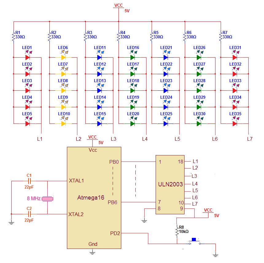
Circuit diagram
As you can see, the circuit is built using AVR micro controller ATMega16 and Darlington chip ULN2003A.
-
As shown in figure 5 same colour LEDs are connected in parallel that will make one bunch. There are 7 such LED bunches each of 5 LEDs so total 35 LEDs.
-
All this LED groups are connected to PORTB through Darlington chip ULN2003A. UNL2003A is used as current driver to provide enough current to LEDs.
-
PORTB pins PB0 to PB6 are connected to inputs of ULN2003A and outputs of ULN2003A are connected to common cathode of LED bunch.
-
The common anodes of all LED bunches are connected to Vcc through 300E current limiting resistor.
-
One push button is connected to PORTD pin PD2 that generates external interrupt when pressed
-
A 8 MHz crystal with two 22 pF capacitors is connected to crystal input pins that provides basic clock for micro controller operation

Fig. 1: Prototype of AVR ATMega16 based LED Chaser Circuit designed on breadboard
Working and operation:
There are 6 different chasing effects and the effect is changed by pressing button. Initially when project is turned ON the 1st chasing effect will start. It will continue till button is not pressed. As the button is pressed the interrupt is generated and the controller will switch to 2nd chasing effect. Similarly by pressing button second time, third time and likewise it will change the 3rd , 4th , 5th and 6th chasing effect. Once again if button is pressed the micro controller will start 1st chasing effect. Now let us see which are these different chasing effects.
1st chasing effect: this is the simplest chasing effect. It blinks all LEDs at 10 Hz for 5 sec and than it blinks alternet LEDs at 10 Hz for 5 sec and repeat this continuously.
2nd chasing effect: it will turn ON one by one LED from left to right and then from right to left
3rd chasing effect: it will vary the intensity of alternet LEDs from max to min and from min to max. Like when L1, L3, L5 and L7 LED bunches having max intensity, L2, L4 and L6 have min intensity. Then slowly L2-L4-L6 intensity increases and reaches to max while L1-L3-L5-L7 intensity decreases and reaches to min. This cycle continuous.
4th chasing effect: this effect is same as 2nd but slight change is it will turn ON two LEDs at a time from left to right and again from right to left.
5th chasing effect: this effect will turn ON all LEDs one by one from left to right and then turn them OFF from right to left
6th chasing effect: this effect will turn on all LEDs from both sides to centre and turn them off from centre both to side.
All the above chasing effect are due to the program downloaded into internal FLASH of ATMega16 micro controller.
Software program:
The program is written in C language. It is compiled using AVR studio software tool. It is simulated using AVR simulator 2 for ATmega16 device available with AVR studio software. Here is the C program code
You may also like:


Project Source Code
###
#include
#include
#include
unsigned int j,count=0,new_effect_flag=0;
unsigned char byt,byt1;
void delay(unsigned int d1)
{
unsigned int x;
for(x=0;x
_delay_us(2);
}
void effect1()
{
while(new_effect_flag==0)
{
for(j=0;j<25;j++)
{
PORTB = 0x00;
_delay_ms(100);
PORTB = 0xFF;
_delay_ms(100);
}
for(j=0;j<25;j++)
{
PORTB = 0x55;
_delay_ms(100);
PORTB = 0xAA;
_delay_ms(100);
}
}
}
void effect4()
{
unsigned char tmp;
while(new_effect_flag==0)
{
PORTB=0xFF;
_delay_ms(1000);
byt1 = 0xFC; // 1111 1100
byt = 0xFE; // 1111 1110
PORTB = byt1; // 1111 1100
_delay_ms(1000);
for(j=0;j<5;j++)
{
tmp = ~byt; // 0000 0001
byt1 = byt1<<1; // 1111 1000
PORTB = byt1 | tmp;
byt = byt<<1; // 1111 1100
_delay_ms(1000);
}
byt1 = 0x1F; // 0001 1111
byt = 0x7F; // 1011 1111
byt = byt>>1;
for(j=0;j<5;j++)
{
tmp = ~byt; // 0100 0000
byt1 = byt1>>1; // 0000 1111
PORTB = byt1 | tmp;
byt = byt>>1;
_delay_ms(1000);
}
}
}
void effect2()
{
while(new_effect_flag==0)
{
PORTB=0xFF;
_delay_ms(1000);
byt1 = 0xFE; // 1111 1110
PORTB = byt1; // 1111 1110
_delay_ms(1000);
for(j=0;j<6;j++)
{
byt = ~byt1; // 0000 0001
byt1 = byt1<<1; // 1111 1100
PORTB = byt1 | byt;
_delay_ms(1000);
}
byt1 = 0x7F;
for(j=0;j<6;j++)
{
byt = ~byt1; // 0000 0001
byt1 = byt1>>1; // 1111 1100
PORTB = byt1 | byt;
_delay_ms(1000);
}
}
}
void effect3()
{
unsigned int a,b,a1;
while(new_effect_flag==0)
{
for(a=10;a<100;a++)
{
a1 = 100-a;
for(b=0;b<10;b++)
{
PORTB = 0x55;
delay(a);
PORTB = 0xAA;
delay(a1);
}
}
for(a=99;a>10;a--)
{
a1 = 100-a;
for(b=0;b<10;b++)
{
PORTB = 0x55;
delay(a);
PORTB = 0xAA;
delay(a1);
}
}
}
}
void effect5()
{
while(new_effect_flag==0)
{
PORTB=0xFF;
_delay_ms(1000);
PORTB=0xFE;
_delay_ms(1000);
for(j=0;j<6;j++)
{
PORTB=PORTB<<1;
_delay_ms(1000);
}
byt1 = 0xFE;
byt = ~byt1;
PORTB = byt;
_delay_ms(1000);
for(j=0;j<6;j++)
{
byt1 = byt1<<1;
byt = ~byt1;
PORTB = byt;
_delay_ms(1000);
}
}
}
void effect6()
{
while(new_effect_flag==0)
{
PORTB = 0xFF;
_delay_ms(100);
PORTB = 0x3E;
_delay_ms(100);
PORTB = 0x1C;
_delay_ms(100);
PORTB = 0x00;
_delay_ms(100);
PORTB = 0x1C;
_delay_ms(100);
PORTB = 0x3E;
_delay_ms(100);
}
}
int main(void)
{
DDRB=0xFF;
MCUCR = (1<
GICR=(1<
sei();
while(1)
{
new_effect_flag=0;
switch(count)
{
case 0:
effect1();
break;
case 1:
effect2();
break;
case 2:
effect3();
break;
case 3:
effect4();
break;
case 4:
effect5();
break;
case 5:
effect6();
break;
case 6:
count=0;
break;
}
}
}
ISR(INT0_vect)
{
count++;
new_effect_flag=1;
_delay_ms(200);
}###
Circuit Diagrams
Project Video
Filed Under: AVR, Electronic Projects
Filed Under: AVR, Electronic Projects

Questions related to this article?
👉Ask and discuss on Electro-Tech-Online.com and EDAboard.com forums.
Tell Us What You Think!!
You must be logged in to post a comment.