Metal detectors offer several useful applications. A few examples include:
- Security checks
- Positioning detection for production equipment
- Elevator floor control
- Mineral prospecting
- Unearthing relics and artifacts
- Collecting traffic statistics
- Metallic waste detection
- Game entertainment
Each detection circuit employs different electronic components and designs. A simple metal detector can be constructed using an RLC circuit.
In this project, we’ll design a metal detector using an RC-A-354 metal sensor — which also uses an RLC circuit for metal detection.
How metal detectors work
Although different designs exist, a metal detector essentially consists of two coils of wire (where one is a transmitter and the other is a receiver). When current flows through one coil, a magnetic field is generated around it.
In a metal detector, current spikes pass through the transmitter coil. As the detector moves over the ground or objects, the magnetic field also moves around with it.
When the transmitter coil is near a metallic object, an eddy current is induced in the metallic object due to the magnetic field of the transmitter coil. This current produces another magnetic field around the metallic object, which is detected by the receiver coil.
When a magnetic field is induced in the receiver coil, a voltage is generated across it and current flows through it. The receiver coil is connected to a circuit that measures any change in the magnetic field, which indicates the presence of current in the receiver coil — by actuating a buzzer or a speaker.
Metal detectors are used to locate metal objects or to identify specific metals. The detector consists of a handheld unit with a sensor probe. Typically, the sensor probe houses the transmitter and receiver coils. The other part of the unit houses the circuit for measuring magnetic fields and an indicator, which can be an LED light, a buzzer, or speakers.
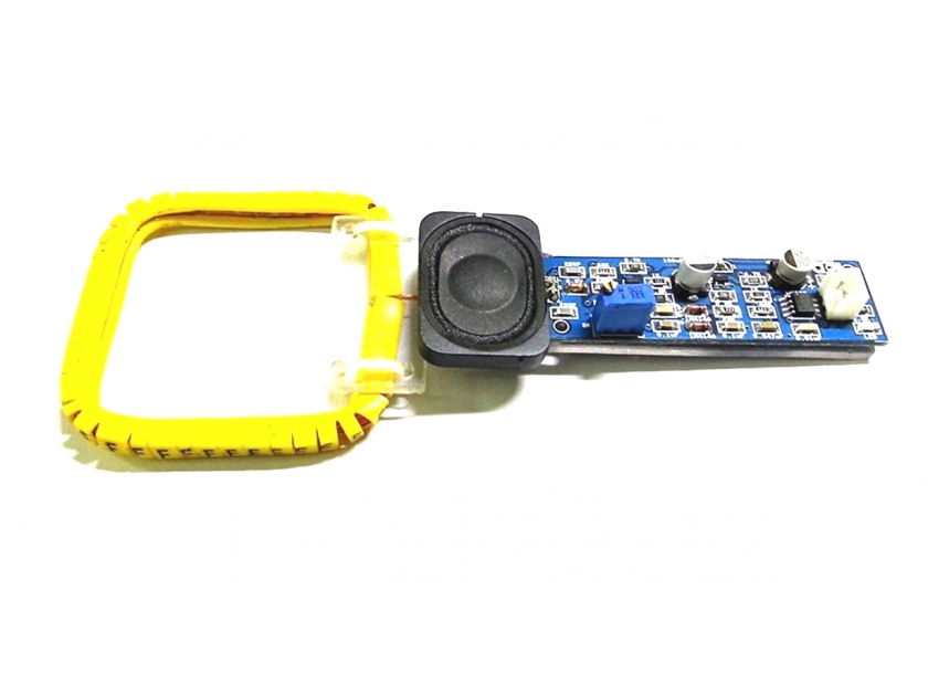
The RC-A-354 sensor
The RC-A-354 sensor is a popular metal detector that uses an RLC circuit. It can search metals up to a distance of 3cm. At this range, it’s useful for security checks or collecting metallic trash.
This sensor has a copper coil about one-meter-long that serves as the inductor. It has:
- Two capacitors: 100 and 47uF
- A NE555 IC
- A 5K potentiometer
- Two IN4148 diodes
- LED indicators
- A buzzer
The RC-A-354 operates via a DC 5V~9V power supply, which means it can be powered by a battery or a microcontroller, such as Arduino.
The NE555 IC works as a square-wave generator, which produces pulses. The sensor’s circuit is responsible for metal detection and is an RLC network that’s formed by the inductor coil, a resistor, and a capacitor. The sensor’s module includes a 5K pot that’s used to adjust the range (of up to 3cm).
When the RC-A-354 sensor is powered on by the DC supply, a green LED is turned ON, and the NE555 generates current spikes in the transmitter coil. These alternating pulses create a magnetic field in the transmitter coil. When the sensor is near a metallic object, this magnetic field induces an eddy current.
The metallic object produces another magnetic field — when near the coil, but not directly at the center of it (or detection will not occur). This secondary magnetic field is detected by the receiver coil, which actuates the buzzer.
The sensor module has an additional transistor circuit that drives the LED indicator. The indicator turns RED when metal is detected. Otherwise, it stays off.
The module also has an output header, which connects to a microcontroller or an application-based circuit. The output is active HIGH. (When the sensor detects metal, the output is set to HIGH. Otherwise, it remains LOW.
The logical output can be useful in several situations. For example, if designing a robot to collect the metallic trash from a garden, the output can be used to stop the robot and actuate a crane.
For this project, we’ll blink an LED light to a similar situation.
Components required
1. Arduino UNO x1
2. RC-A-354 metal sensor x1
3. Battery 9V x1
4. LED x1
5. Resistor 330Ω x1
6. Breadboard x1
7. Connecting or jumper wires
Circuit connections
To start, connect a 9V battery to the RC-A-354 sensor’s DC supply. In the sensor’s output terminal, connect the output to Arduino’s pin 2 and the GND to any of Arduino’s ground pins.
Next, connect an LED at Arduino’s pin 3 with a 330Ω current-limiting resistor in series. Remember to adjust the pot on the sensor module according to the required range.

Arduino sketch
const int metalSensor = 2;
const int LED = 3;
void Blink_LED(){
for(int i = 0; i<10; i++)
{
digitalWrite(LED, HIGH);
delay(500);
digitalWrite(LED, LOW);
delay(500);
}
}
void setup() {
pinMode(metalSensor, INPUT_PULLUP);
pinMode(LED, OUTPUT);
digitalWrite(LED, LOW);
Serial.begin(9600);
}
void loop() {
if(digitalRead(2) == HIGH)
{
Blink_LED();
Serial.println(“Metal Detected!!”)
}
else
{
digitalWrite(LED, LOW);
}
How it works
When the search probe moves near a metallic object, the RC-A-354 sensor outputs a “beep” through the onboard buzzer and a green LED begins flashing. The buzzer is already connected within the sensor module, so there’s no need to connect it with Arduino to receive this indication.
The sensor has a logical output, which is active HIGH. This output is used to blink the LED whenever the sensor detects a metallic object. The LED on the breadboard is connected so that it turns ON when it sinks current from Arduino’s pin through a HIGH logic. It turns OFF when Arduino’s pin has a LOW logic output.
The code
The sketch begins by assigning a pin to the LED output. This pin is also connected to the RC-A-354 sensor’s output.
The function, Blink_LED(), is defined to “blink” the LED. In the setup() function, the sensor pin is configured as the input and the LED pin is configured as the output. The LED is turned OFF by writing a LOW logic to the LED pin.
The baud rate for serial messaging is set to 9600 bps. In the loop() function, the logical output from the metal detector sensor is monitored in an “if” clause. If Arduino detects a HIGH from the sensor, the Blink_LED() function is called and a message, “Metal Detected!!” is printed serially. Otherwise, the blinking LED remains OFF.
Results
You may also like:


Filed Under: Arduino, Arduino., Electronic Projects, Sensors, Tutorials, Video

Questions related to this article?
👉Ask and discuss on Electro-Tech-Online.com and EDAboard.com forums.
Tell Us What You Think!!
You must be logged in to post a comment.