A very common feature in Android and iOS fitness apps is calculating the number of steps the user walks and the distance he covers. These apps calculate the number of steps walked by the user either using GPS location and manipulating the geospatial data or by monitoring the acceleration vector of the device using an accelerometer sensor.
In this project, we have designed a similar walking steps calculator on the Arduino platform. The method used in this project is monitoring the acceleration vector of the device. For this purpose, the ADXL345 accelerometer is interfaced with the Arduino. The number of steps walked by the user and the distance covered by him are displayed on an OLED screen. The logic used in this project can be easily replicated in a smartwatch application. You can easily port the code logic to any other language as it simply reads the data from the accelerometer sensor and manipulates that data to detect the user’s movement.
Components required
- Arduino UNO x1
- ADXL345 Accelerometer Sensor x1
- SSD1306 OLED display x1
- Connecting wires/Jumper wires
Circuit connections
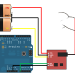
For designing this project, the ADXL345 accelerometer sensor and SSD1306 OLED are interfaced with the Arduino. To do this, connect its GND and VCC pins to Arduino’s ground and 3.3V out pins. Then connect the SDA and SCL pins of the accelerometer sensor to the SDA and SCL pins on the I2C port of the Arduino.
In this project, a 7-pin SSD1306 OLED module is interfaced to Arduino UNO. The module is connected to the Arduino as follows.
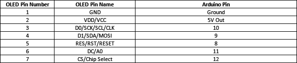
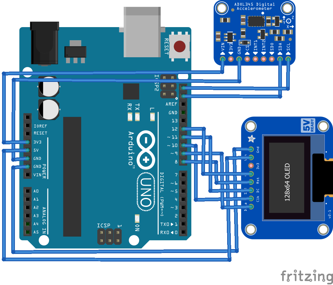
Circuit Diagram of Arduino-based Pedometer
Arduino sketch
How it works
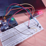
When the device is powered on, the SSD1306 OLED display is initialized, and the logo of “EEWORLDONLINE” and the device name “Steps Counter” are flashed on the screen. The initial number of steps is displayed to be 0, and the distance covered is also displayed as 0. Now, all the user needs to do is keep the device on their person.
The device continuously monitors its acceleration vector with the help of the ADXL345 accelerometer sensor. When the user walks, there is a change in the acceleration vector. When the user steps a foot forward, the immediate change in acceleration vector goes negative. As the user steps the other foot balancing on the previous foot, the immediate change in acceleration vector goes positive.
Average acceleration values are calculated as the device is powered on and initial messages are flashed on the screen. The average values are also derived by taking the mean of 50 consecutive readings from the ADXL345 accelerometer. These average values for the acceleration of the device in the x-, y-, and z-axis serve as the reference point.
After the initial setup is complete, the device again calculates the acceleration in x-, y-, and z-axis 50 consecutive times and derives an average of those values. The acceleration vector of the device is calculated by taking the square root of the difference of current acceleration values compared to reference values.
After a delay of 250 milliseconds, the device again calculates the acceleration in x-, y-, and z-axis for 50 consecutive times and derives the average of those values. The acceleration vector of the device is calculated once again at an interval of 250 ms by taking the square root of the difference of current acceleration values compared to reference values. The difference between the acceleration vector now and the acceleration vector 250 ms before is calculated, and if the difference is more than 0.05, a step is incremented. The value of distance covered is calculated by multiplying the number of steps by one foot or 0.3048 meters, assuming that an average step is one foot long.
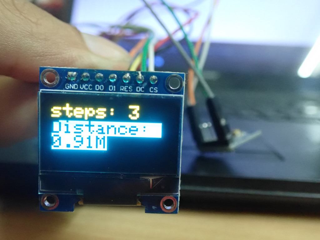
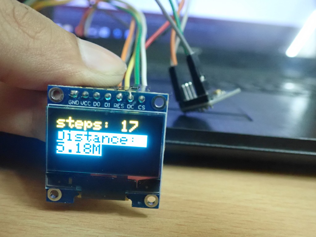
The number of steps and distance covered are updated on the OLED screen, with a delay of 400 ms. The process of calculating the difference between two consecutive acceleration vectors of the device at an interval of 250 ms is continued throughout to monitor the user’s movement.
It should be noted that the delay of 250 ms between the calculation of two consecutive averaged acceleration vectors and the difference of 0.05 is obtained after careful calibration of the device.
Check out this link to learn more about how the ADXL345 accelerometer communicates with Arduino over the I2C protocol.
To learn more about interfacing SSD1306 OLED with Arduino, check out this link.
You should note that Arduino’s reset button acts as a reset button for the device and reset the number of steps and distance covered to zero.
The code
The code begins by importing wire.h for I2C communication with the ADXL345 accelerometer sensor and SPI.h for communication SSD1306 OLED display. The Adafruit libraries for working with OLED display are imported and the constants required for OLED interfacing and defined parameters. An object display is initialized for the SSD1306 class. The bitmap for the logo of EEWORLDONLINE is stored in Arduino’s PROGMEM and is converted to an array object. The variables to store average, current, and immediately next acceleration values are declared. A variable to store the number of steps is declared.
In the setup() function, three different functions are called. The ssd1306_init() is called to initialize the SSD1306 OLED display and flash initial messages onto it. The adxl345_init() is called to initialize the acceleration sensor. The read_av_acc() function is called to calculate reference acceleration values when the device is at rest.
In the loop() function, the acceleration vector is calculated twice at a gap of 250 ms, and if the difference between two values of greater than 0.05, one step is incremented. The number of steps and distance covered are updated to OLED display.
Result
Demonstration Video
You may also like:


Filed Under: Arduino, Arduino., Electronic Projects, Sensors, Tutorials, Video

Questions related to this article?
👉Ask and discuss on EDAboard.com and Electro-Tech-Online.com forums.
Tell Us What You Think!!
You must be logged in to post a comment.