Engineers Garage

  • Projects and Tutorials
    • Circuit Design
    • Electronic Projects
      • 8051
      • Arduino
      • ARM
      • AVR
      • PIC
      • Raspberry pi
      • STM32
    • Tutorials
    • Components
  • Articles
    • Tech Articles
    • Insight
    • Invention Stories
    • How to
    • What Is
  • News
    • EE Design News
    • DIY Reviews
    • Guest Post
    • Sponsored Content
  • Forums
    • EDABoard.com
    • Electro-Tech-Online
    • EG Forum Archive
  • Digi-Key Store
    • Cables, Wires
    • Connectors, Interconnect
    • Discrete
    • Electromechanical
    • Embedded Computers
    • Enclosures, Hardware, Office
    • Integrated Circuits (ICs)
    • Isolators
    • LED/Optoelectronics
    • Passive
    • Power, Circuit Protection
    • Programmers
    • RF, Wireless
    • Semiconductors
    • Sensors, Transducers
    • Test Products
    • Tools
  • EE Resources
    • DesignFast
    • LEAP Awards
    • Oscilloscope Product Finder
    • Video
    • White Papers
    • Webinars
  • EE Learning Center
  • Women in Engineering

Serial data received from pc and displayed on 16×2 lcd using 8051(89c51,89c52) microcontroller UART port

February 11, 2021 By EG Projects

In this post i am going to explain how to receive serial data from your pc and display it on 16×2 lcd using 89c51 microcontroller UART port. Hardware components of the project includes max232(TTL to RS232 level converter/shifter ), 8051(89c51,89c52) microcontroller and 16×2 lcd. On software side i am using Hyper terminal. Hyper terminal is a program through which one can transmit and receive data serially using personal computer(PC) serial ports. Standard  PC has two serial ports, db-9 and db-25. To these serial ports we usually connect our printers, fax machines, mouse and joy sticks.
The block diagram of data transfer between 89c51 microcontroller UART port and personal computer is shown below. 

8051 microcontroller serial data transfer between pc and 89c51 uart port

8051 microcontroller serial data transfer between pc and 89c51 uart port

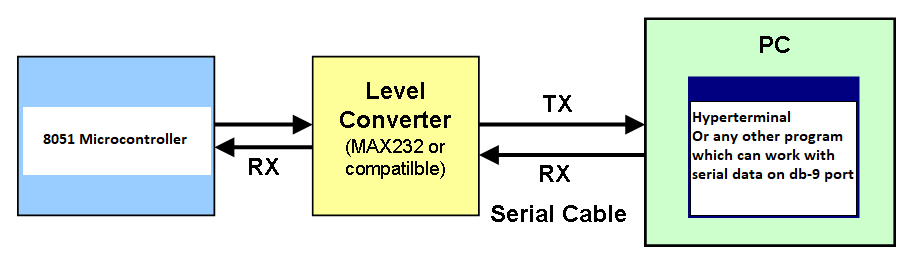
Max232 Level converter

8051 microcontroller works on TTL logic and personal computers works on rs232 logic. In order to communicate between the two modules data must be on the same carrier logic. Hence a level shiftier like max232 is used. Which transforms data from one logic to another before sending it to the receiver. In order to learn more about max232 transceiver, its pin out, working and power requirements please take the below tutorial. 

Max232 Pin out and Working

8051(89c51,89c52) Microcontroller UART

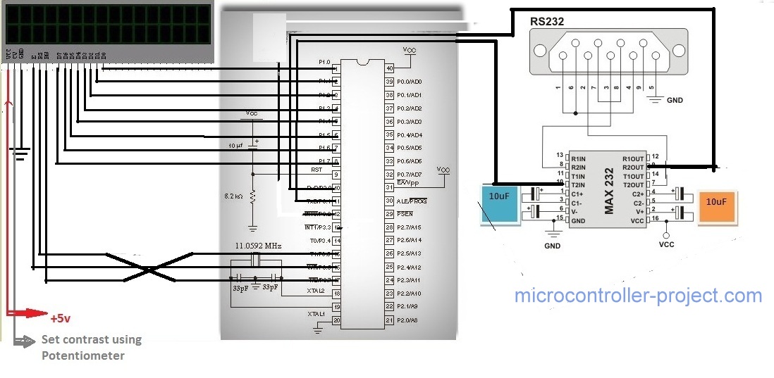
89c51 microcontroller Uart is used to receive data from PC. You can also use any other 8051 series microcontroller like 89c52 microcontroller. But first be sure it has build in UART(universal asynchronous receiver transmitter)for serial communication.

Port-1 of our microcontroller is used as output Port. It is connected to data pins of 16×2 lcd. 

  • Port-3 pin# 5 is connected to rs(regester select) pin of 16×2 lcd. 
  • Port-3 pin# 6 is connected to en(enable) pin of 16×2 lcd. 
  • Port-3 pin# 7 is connected to rw(read write) pin of 16×2 lcd.

If you dont know how to interface lcd with 8051(89c51,89c52) microcontroller here are some good tutorial, just go through them.

  • 16×2 LCD WORKING.
  • DIFFERENCE BETWEEN COMMANDS AND DATA SEND TO LCD.
  • DISPLAYING YOUR NAME ON LCD using 8051 MICROCONTROLLER.

serial data receiverd from pc hyperterminal and displayed on lcd using 8051(89c51,89c52) microcontroller

serial data receiverd from pc hyperterminal and displayed on lcd using 8051(89c51,89c52) microcontroller

Project Code

In the main function i first called the lcdinit() function to initialize the 16×2 lcd. All the commands used in the function  are deeply discussed in the above tutorials. Then timer mode is set. TMOD=0x02 means Timer1,  Mode2 (8 bit auto reload) is selected. TH1=0xFD is actually timer one high byte, giving 0xFD hexadecimal value to TH1 means setting communication baud rate between 8051 microcontroller and PC to 9600 bps(bits per second). SCON=0x50 is actually setting our serial data bits format Total=8 Data bit with 1 start bit and 1 stop bit. TR1=1 means run timer one. This whole phenomena with full meaning of the statements (SCON,TMOD,TH) is discussed in the below two tutorials. How to calculate baud rate values are also discussed.

  • HOW TO SEND SERIAL DATA TO PC(Hyperterminal).
  • TIMER REGISTERS OF 8051(89c51).

while(RI==0) is checking RI(receive interrupt) flag continuously. This flag automatically becomes one when 8051(89c51,89c52) receives any data on its RXD pin(P3^0). when RI becomes 1 it means we have one byte of data in our SBUF(serial buffer) register. So in next statement i picked the Byte from SBUF register and save it in character variable data. Then i made the RI flag low again to receive next byte. The Byte which i saved in data variable is now send to display function to be displayed on the 16×2 lcd. 

Download the project files and Code(Hex,c++) compiled using keil uvision 4 compiler. If you feel any problem in the code or don’t understand any statement of the code just write your queries below. The code is Tested using Hardware and its free of any bug. << />iv>
Serial data Received from PC 

Related Articles Read More >

Remote Controlling Multiple Loads Using RF Module (Part 2/23)
Increasing Range of RF Module by Increasing Transmission Power (Part 3/23)
Increasing range of RF module by using antenna (Part 4/23)
Increasing the Range of RF Module by Using Antenna and Increasing Transmission Power (Part 5/23)

Featured Tutorials

  • Remote Controlling Multiple Loads Using RF Module (Part 2/23)
  • Increasing Range of RF Module by Increasing Transmission Power (Part 3/23)
  • Increasing range of RF module by using antenna (Part 4/23)
  • Increasing the Range of RF Module by Using Antenna and Increasing Transmission Power (Part 5/23)
  • Controlling Multiple RF Receivers by Universal RF Transmitter (Part 6/23)
  • Multiple RF Receivers Controlled by a Universal RF transmitter based on Address Pin Configuration (Part 7/23)

Stay Up To Date

Newsletter Signup

EE Training Center Classrooms

“ee

“ee

“ee

“ee

“ee

Recent Articles

  • IAR Systems announces IEC and ISO certifications of its RISC-V development tools
  • Mathematical equations executed by an MCU
  • Infineon’s new Wi-Fi 6 brings reliable connectivity to smart homes
  • Toshiba releases compact LDO regulators for stabilizing DC power lines
  • Clap sensor using STM32 MCU
...

RSS EDABOARD.com Discussions

  • Stumped with buck converter simulation Pspice
  • CMCON0 and ANSEL registers
  • Smart high side switch is a 200mA current clamp device?
  • Finding Difficulty in Selection LED MATRIX
  • MCLR as digital input is resetting the device

RSS Electro-Tech-Online.com Discussions

  • Identify Crystal on Ford Immobilizer antenna board
  • GPU price, lol
  • Diode that only allows continuity at 13.5v?
  • ZVS driver circuit
  • Cutting D-shaped and double flat holes
Engineers Garage
  • Analog IC TIps
  • Connector Tips
  • DesignFast
  • EDABoard Forums
  • EE World Online
  • Electro-Tech-Online Forums
  • Microcontroller Tips
  • Power Electronic Tips
  • Sensor Tips
  • Test and Measurement Tips
  • 5G Technology World
  • About Us
  • Contact Us
  • Advertise

Copyright © 2021 WTWH Media LLC. All Rights Reserved. The material on this site may not be reproduced, distributed, transmitted, cached or otherwise used, except with the prior written permission of WTWH Media
Privacy Policy | Advertising | About Us

Search Engineers Garage

  • Projects and Tutorials
    • Circuit Design
    • Electronic Projects
      • 8051
      • Arduino
      • ARM
      • AVR
      • PIC
      • Raspberry pi
      • STM32
    • Tutorials
    • Components
  • Articles
    • Tech Articles
    • Insight
    • Invention Stories
    • How to
    • What Is
  • News
    • EE Design News
    • DIY Reviews
    • Guest Post
    • Sponsored Content
  • Forums
    • EDABoard.com
    • Electro-Tech-Online
    • EG Forum Archive
  • Digi-Key Store
    • Cables, Wires
    • Connectors, Interconnect
    • Discrete
    • Electromechanical
    • Embedded Computers
    • Enclosures, Hardware, Office
    • Integrated Circuits (ICs)
    • Isolators
    • LED/Optoelectronics
    • Passive
    • Power, Circuit Protection
    • Programmers
    • RF, Wireless
    • Semiconductors
    • Sensors, Transducers
    • Test Products
    • Tools
  • EE Resources
    • DesignFast
    • LEAP Awards
    • Oscilloscope Product Finder
    • Video
    • White Papers
    • Webinars
  • EE Learning Center
  • Women in Engineering