[[wysiwyg_imageupload:1931:]]The report is contributed by P. Srinivasan from Neyveli. He recently Completed his B.E in Electrical & Electronics Engineering from Ponnaiyah Ramajayam College of Engineering & Technology, Tanjore.
1. INTRODUCTION
Neyveli lignite corporation limited was registered as a company on 14th November 1956.The mining operations in Mines were formally inaugurated on 20th may 1957 by our prime minister Mr. Pandit Jawaharlal Nehru.
Neyveli lignite corporation limited (NLC) consist of Mine I, Mine II & Mine IA. It also consists of Thermal Power Station I , Thermal Power Station IA and Thermal Power Station II. We are doing our project in Thermal Power Station II.
1.1 THERMAL POWER STATION-II
TPS-II has been a major power source of power to all southern states of India. The 1470mw capacity power station consists of 7 units of 210mw each. The power station was constructed in 2 stages in 630mw and 840mw.The first 210mw unit was synchronized in March 1986 and the last unit in June 1993.This power station has seen a series of technologies innovation such as
1.1.1 SPECIAL FEATURES
· Largest Thermal Power Station in Asia.
· First and largest Tower type Boiler in the country (92.7mw).
· First largest Boiler Management System.
· 124 meters natural draught cooling towers.
· 220 metres tall chimney for wide disposal of gases.
· Distributed digital control system, data acquisition system for control and instrumentation.
· The power generated from TPS-II after meeting the needs of the MINE-II is shared by the Southern States viz, TamilNadu, Kerala, Karnataka, A.P and union territory of Pondicherry.
1.2 POWER ALLOCATION
Andhra Pradesh – 19%(277mw)
Karnataka – 14%(199mw)
Kerala – 10%(155mw)
TamilNadu – 30%(441mw)
Pondicherry – 5% (80mw)
N.O ` – 7%(100mw)
UN allocated share – 15%(220mw).
1.3 DESIGN
The second thermal power station consists of seven numbers of 210mw units and since having installed capacity of 1470mw.Units 1,2&3 were constructed in the 1st stage followed by the stage units 4,5,6&7.Lignite for the station is supplied from Mine-II having an annual capacity of 10.5 million times. The First stage units are fully of foreign origin .
Generators are of M/S ercole marselli; italy’s supply. The second stage units are fully of M/S BHELL’S supply even though the boilers are of M/S EVT Germany’s design and generators are of Russian design. 901401 million unites of electricity can be generated per annum from this power station at 70 % annual plant load factor(PLF)but the actual production figures in recent years are much higher. 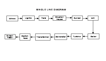

Fig no 1.3: Single line diagram
2. ELECRICAL SYSTEMS
Stage-I generators are hydrogen cooled. The generating voltage is 15kV, which is stepped up to 230kV. In stage-II, the generator has a stator water-cooling system. Rotor and other parts are hydrogen cooled. The generating voltage is 15.75kV, which is stepped up to 400kV. Static excitation is also employed. Two hydrogen plants supply hydrogen for the generators. On 230kV, there are 10 feeders, on 400kV side there are 5 feeders. A switchyard control room regulated the power flow. Each unit has a control room with elaborate protection, interlocks, control circuits and instruments. Data acquisition system is employed in Stage-I whereas Distributed Digital Control is available for Stage-II units.
2.1 210MW GENERATOR SPECIFICATIONS
Active power = 210 MW
MVA rating = 247 MVA
Reactive power = 130 MVAR
Power factor = 0.85 lagging
Voltage = 15 kV
Current = 9507A
Frequency = 50Hz
Speed = 3000 rpm
Cooling system = hydrogen cooled
H2 pressure = 3.12 kg/cm2
Excitation voltage = 340V
Excitation current = 2854A.
In electricity generation, an electrical generator is a device that converts mechanical energy to electrical energy, generally using electromagnetic induction. A generator forces electric charges to move through an external electrical circuit, but it does not create electricity or charge, which is already present in the wire of its winding.
3. COOLING PROCESS
The generator losses are dissipated as heat through stator and rotor bodies. An efficient, ventilating system is needed to keep the temperature of the windings resulting due to various losses below certain limits depending upon insulation. Also the demand for increased output from a single generator necessitated improved methods of cooling to keep the size of the generator with in the reasonable limits, to minimize losses and to improve efficiency of generator.
The primary cooling medium is air or hydrogen, which in turn is passed through a water cooled heat exchanger (gas cooler). Building of air cooled turbo generators above 50 MW rating presented serious ventilation difficulties, not only in circulating requisite quantity of air through the machine, but also because the high fan power required to circulate the air. The cooling system shall also ensure that no excessive hot spots occur at windings/core. As the single largest loss in the generator is the windage loss, the air must be replaced with a lighter gas. Hydrogen has a great advantage that its density at atmosphere pressure is only 1/14th of that of air. So, windage loss can be reduced in the same ratio. Because of many other properties like specific heat, density, thermal conductivity etc., hydrogen is widely used as coolant in large turbo-alternators.
3.1 ADVANTAGES OF HYDROGEN COOLING
- Windage and ventilating losses are reduced due to the low gas density.
- An increased output per unit volume of active material because of the high thermal conductivity and high heat transfer co-efficient of hydrogen.
- The life of the insulation on the stator winding is increased because of the absence of oxygen, moisture and the corona discharge.
- The reduction of windage noise, dirt and moisture because of lesser density of gas and closed recirculation.
- Because of the hydrogen atmosphere inside the generator, the chances of fire are reduced as hydrogen cannot support combustion or oxidization.
3.1.1 PRODUCTION OF HYDROGEN
Hydrogen is the most abundant chemical element, constituting roughly 75% of the universe’s elemental mass. Hydrogen may be produced from water by electrolysis at substantially greater cost than production from natural gas. The electrolysis of water is a simple method of producing hydrogen. A low voltage current is run through the water, and gaseous oxygen forms at the anode while gaseous hydrogen forms at the cathode. Typically the cathode is made from platinum or another inert metal when producing hydrogen for storage. If, however, the gas is to be burnt on site, oxygen is desirable to assist the combustion, and so both electrodes would be made from inert metals.
3.1.2 APPLICATIONS OF HYDROGEN
§ H2 is used as the rotor coolant in electrical generators at power stations, because it has the highest thermal conductivity of any gas.
§ Since H2 is lighter than air, having a little more than 1/15th of the density of air, it was once widely used as a lifting gas in balloon.
§ In more recent applications, hydrogen is used pure or mixed with nitrogen (sometimes called forming gas) as a tracer gas for minute leak detections and airships.
§ Applications can be found in the automotive, chemical, power generation, aerospace, and telecommunication industries.
§ The chances of fire are reduced as hydrogen cannot support combustion or oxidization.
3.2 HYDROGEN GAS SYSTEM
Hydrogen treatment plant supplies hydrogen to the generator for cooling purpose. The hydrogen gas is transferred in cylinders at a pressure of 150 kg/cm2. The pressure is reduced to 3.5 kg/cm2 and supplied at the top portion of the generator. The generator gets heated up due to various losses and the huge amount of current flowing through the stator. Hydrogen absorbs the heat generated and in turn, it gets heated up.
The hydrogen gas is now termed as the “HOT GAS”. The air blower (fan) collects the hot gas and forces it towards the cooler (fig 2.1).
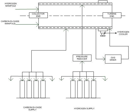 Fig no 3.2 : Hydrogen gas system
Two vertical coolers are being placed at the turbine end. The cooler consists of many tubes through which chill water flows. The hot gas passes through the coolers and gets cooled. Once the gas is cooled, it is being termed as “COLD GAS”. The chill water, flowing in the tubes, inside the cooler, is being controlled by two valves (70% valve and 30% valve). The 30% valve is an auto valve which is controlled by using a microprocessor. The 70% valve is being controlled manually.
4. EXISTING SYSTEM
4.1 EXISTING SYSTEM CIRCUIT DIAGRAM
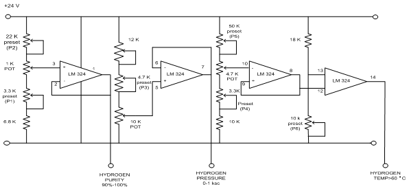
Existing system circuit diagram is shown in Circuit Diagram Tab 1
4.2 CIRCUIT OPERATION
The circuit consists of three stages to provide the parameters such as hydrogen purity, hydrogen pressure and temperature of the gas. The circuit (Circuit Diagram tab1) is fed by 24V DC supply and the operational amplifiers used in the circuit are IC 324.
The first stage operational amplifier is a unity gain amplifier that provides purity from 90% – 100%. The operational amplifier is preset to 90%, then by varying the POT we get variations from 90% – 100% analog output.The input is given to non-inverting terminals of the op-amp used and the output is fed back to inverting terminal of the op-amp.
The second stage op-amp is a unity gain amplifier, provided to get pressure variations from 0 – 1KSC. By varying the POT, the input to the non-inverting terminal of the op-amp is varied and correspondingly we get variation from 0 to 1 KSC, analog output.
The third stage consists of two op-amps, one is used as unity gain amplifier and the other one is used as comparator to give digital output. The unity gain amplifier is initially preset to 60°C. The analog output from the unity gain amplifier is fed to the non-inverting terminal of the comparator. When the set level is crossed, the comparator gives high output or else it gives low output.
The parameters derived from these circuits are percentage of hydrogen purity, hydrogen pressure and the temperature of the gas.
4.3 BLOCK DIAGRAM 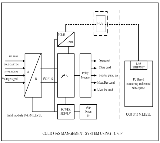

Fig no 4.3: Block diagram
4.3.1 DESCRIPTION
The circuit consists of a microcontroller (89C52) which is the main controlling unit. Special sensors are being used to measure hydrogen temperature, hydrogen pressure, seal oil pressure and voltage signals .An analog to digital converter (ADC 8591) is implemented to convert analog signals such as hydrogen temperature, pressure, seal oil pressure and voltage signals to their corresponding digital signals. The output from ADC is fed to the microcontroller unit.
The output from ADC sets some port pins to be ON or OFF based on the field temperature. Correspondingly, the ports will operate some relays. The relays control the operation of valves which are responsible for controlling the amount of cooling water entering into the cooler. Power supply module supplies input power to all the components. RS232 is being used for serial communication purpose. SCADA is used for monitoring purpose.
4.3.2 CIRCUIT LOGIC
1.If the cold gas temperature ‘T’ is 44°C, NORMAL operation is performed.
2.If the cold gas temperature is above 45°C, then the open command is given so that water flow increases and reduced the temperature to the set temperature.
3.If the cold gas temperature is below 45°C, then the close command is given so that water flow decreases and increased the temperature to the set temperature.
4.If there is increase in temperature, even after open command is given then Hydrogen pump is started which increases the rate of flow of cooling water and improves cooling process.
5.Further increase in cold gas temperature is being controlled by
Implementing MVAR decreament (or)MVAR increament command.
6. If all the above measures fail in controlling the cold gas temperature, then unit should be tripped.
5. PROPOSED SYSTEM
5.1 CIRCUIT DIAGRAM
Circuit diagram of proposed system is shown in Circuit Diagram tab2.
5.2 DESCRIPTION
5.2.1 POWER SUPPLY MODULE
Power supplies, often referred to as “switching power supplies”, use switcher technology to convert the AC input to lower DC voltages. The typical voltages supplied are:
· 3.3 volts
· 5 volts
· 12 volts
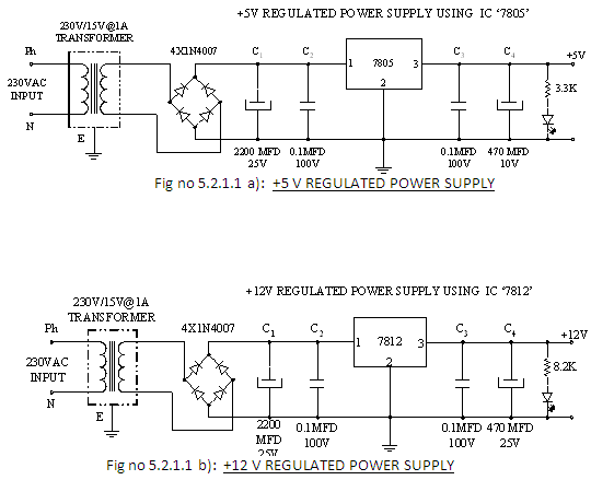
The 3.3- and 5-volts are typically used by digital circuits, while the 12-volt is used to run motors in and disk drive fans. We are utilizing for the same, the most cheapest and commonly available energy source of 230v-50Hz and stepping down, rectifying, filtering and regulating the voltage.
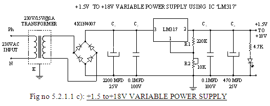
5.2.1.1 CIRCUIT DIAGRAM OF POWER SUPPLY
5.2.1.2 STEP DOWN TRANSFORMER
When AC is applied to the primary winding of the power transformer it can either be stepped down or up depending on the value of DC needed. In our circuit the transformer of 230v/15v is used to perform the step down operation. The current rating of the transformer used in our project is 1A.Apart from stepping down AC voltages, it gives isolation between the power source and power supply circuitries.
5.2.1.3 RECTIFIER UNIT
In the power supply unit, rectification is normally achieved using a four silicon power diodes. A commonly used circuit for supplying large amounts of DC power is the bridge rectifier. The components used in this system require 5V and 12V.So the AC voltage should be converted into required DC voltage. This is known as Rectification. For this purpose a rectifier is used.
5.2.1.4 FILTERING UNIT
Filtering ciruits which usually capacitor is acting as a surge arrester always follow the rectifier unit. This capacitor is also called as a decoupling capacitor or a bypassing capacitor.
· An electrolytic Capacitor C1 of 2200MFD / 25V rating is provided at the output of the rectifier circuit as filter.
· 0.1MFD/100V capacitors are provided in the circuit to bypass the high frequency components of the rectified voltage.
· Capacitor C3 470MFD/25V is provided at the output of the regulator to further smoothen the output.
5.2.1.5 VOLTAGE REGULATORS
The voltage regulator play an important role in any power supply unit. The primary purpose of regulator is to aid the rectifier and filter circuit in providing a constant DC voltage to the device. with a regulator connected to the DC output, the voltage can be maintained within a close tolerant region of the desired output.IC7812 and IC7805 is used in this project for providing +12V and +5V DC supply. The LM317, for example, can be operated with the output voltage regulated at any setting over the range of voltage from 1.2V to 37V.Finally resistance is placed in series with LED for its protection and the LED indicates the availability of regulated output supply.
5.2.2 RELAY MODULE
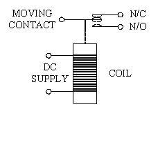 A relay is an electrically operated switch.Current flowing through the coil of the relay creates a magnetic field which attracts a lever and changes the switch contacts. The coil current can be on or off so relays have two switch positions and they are double throw (changeover) switches.Relays allow one circuit to switch a second circuit which can be completely separate from the first. There is no electrical connection inside the relay.Between the two circuits, the link is magnetic and mechanical.
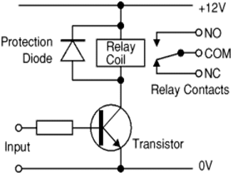
Fig no 5.2.2: Relay module
A transistor is usually used to amplify the small IC current to the larger value required for the relay coil. Relay coils produce brief high voltage ‘spikes’ when they are switched off and this can destroy transistors and ICs in the circuit. To prevent damage you must connect a protection diode across the relay coil.
The relay’s switch connections are usually labelled COM, NC and NO:
- COM = Common, always connect to this, it is the moving part of the switch.
- NC = Normally Closed, COM is connected to this when the relay coil is off.
- NO = Normally Open, COM is connected to this when the relay coil is on.
- Connect to COM and NO if you want the switched circuit to be on when the relay coil is on.
- Connect to COM and NC if you want the switched circuit to be on when the relay coil is off.
5.2.2.1 ULN 2803
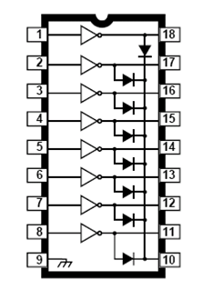
Fig no 5.2.2.1 : ULN 2803
The ULN 2803Ahave series input resistors selected for operation. The ULN 2803A is one of the standard Darlington arrays.
5.2.2.2 FEATURES
§ TTL, DTL, PMOS, or CMOS Compatible Inputs.
§ Output Current to 500 Ma.
§ Output Voltage to 95 V.
§ Transient-Protected Outputs.
§ Dual In-Line Package or Wide-Body Small-Outline Package.
While choosing a relay we should consider the following features:
Physical size and pin arrangement
If you are choosing a relay for an existing PCB you will need to ensure that its
dimensions and pin arrangement are suitable.
Coil voltage
The relay’s coil voltage rating and resistance must suit the circuit powering the relay coil. Many relays have a coil rated for a 12V supply but 5V and 24V relays are also readily available
Coil Resistance
The circuit must be able to supply the current required by the relay coil. You can use Ohm’s law to calculate the current:

Switchratings (voltageandcurrent)
The relay’s switch contacts must be suitable for the circuit they are to control. You will need to check the voltage and current ratings.
Switch contact arrangement (SPDT, DPDTetc)
Most relays are SPDT or DPDT which are often described as “single pole changeover” (SPCO) or “double pole changeover” (DPCO).
5.2.3 MICRO CONTROLLER
5.2.3.1 Features
• Compatible with MCS-51™ Products.
• 8K Bytes of In-System Reprogrammable Flash Memory
• Endurance: 1,000 Write/Erase Cycles
• Fully Static Operation: 0 Hz to 24 MHz
• Three-level Program Memory Lock
• 256 x 8-bit Internal RAM
• 32 Programmable I/O Lines
• Three 16-bit Timer/Counters
• Eight Interrupt Sources
• Programmable Serial Channel
• Low-power Idle and Power-down Modes
5.2.3.2 Description
The AT89C52 is a low-power, high-performance CMOS 8-bit microcomputer with 8K bytes of Flash programmable and erasable read only memory (PEROM). The device is manufactured using Atmel’s high-density nonvolatile memory technology and is compatible with the industry-standard 80C51 and 80C52 instruction set and pinout. The on-chip Flash allows the program memory to be reprogrammed in-system or by a conventional nonvolatile memory programmer. By combining a versatile 8-bit CPU with Flash on a monolithic chip, the Atmel AT89C52 is a powerful microcomputer which provides a highly-flexible and cost-effective solution to many embedded control applications.
5.2.4 BLOCK DIAGRAM : 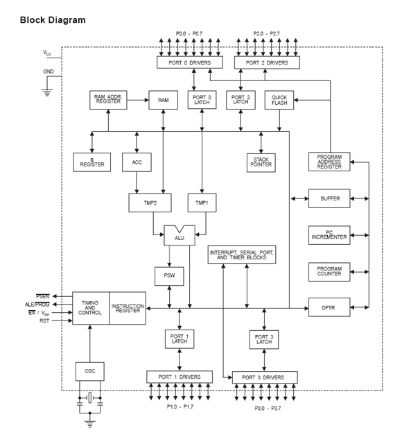

Fig no 5.2.4 : Block diagram of proposed system
5.2.4.1 INTERRUPTS
The AT89C52 has a total of six interrupt vectors: two external interrupts (INT0 and INT1), three timer interrupts (Timers 0, 1, and 2), and the serial port interrupt. Each of these interrupt sources can be individually enabled or disabled by setting or clearing a bit in Special Function Register IE. IE also contains a global disable bit, EA, which disables all interrupts at once.
Timer 2 interrupt is generated by the logical OR of bits TF2 and EXF2 in register T2CON. Neither of these flags is cleared by hardware when the service routine is vectored to. In fact, the service routine may have to determine whether it was TF2 or EXF2 that generated the interrupt, and that bit will have to be cleared in software. The Timer 0 and Timer 1 flags, TF0 and TF1, are set at S5P2 of the cycle in which the timers overflow. The values are then polled by the circuitry in the next cycle. However, the Timer 2 flag, TF2, is set at S2P2 and is polled in the same cycle in which the timer overflows.
5.2.4.2 OSCILLATOR CHARACTERISTICS
XTAL1 and XTAL2 are the input and output, respectively, of an inverting amplifier that can be configured for use as an on-chip oscillator, as shown in Figure 7. Either a quartz crystal or ceramic resonator may be used. To drive the device from an external clock source, XTAL2 should be left unconnected while XTAL1 is driven. There are no requirements on the duty cycle of the external clock signal, since the input to the internal clocking circuitry is through a divide-by-two flip-flop, but minimum and maximum voltage high and low time specifications must be observed.
IDLE MODE
In idle mode, the CPU puts itself to sleep while all the on chip peripherals remain active. The mode is invoked by software. The content of the on-chip RAM and all the special functions registers remain unchanged during this mode. The idle mode can be terminated by any enabled interrupt or by a hardware reset. Note that when idle mode is terminated by a hardware reset, the device normally resumes program execution from where it left off, up to two machine cycles before the internal reset algorithm takes control. On-chip hardware inhibits access to internal RAM in this event, but access to the port pins is not inhibited. To eliminate the possibility of an unexpected write to a port pin when idle mode is terminated by a reset, the instruction following the one that invokes idle mode should not write to a port pin or to external memory.
POWER DOWN MODE
In the power-down mode, the oscillator is stopped, and the instruction that invokes power-down is the last instruction executed. The on-chip RAM and Special Function Registers retain their values until the power-down mode is terminated.
The only exit from power-down is a hardware reset. Reset redefines the SFRs but does not change the on-chip RAM. The reset should not be activated before VCC
DUAL DATA POINTER REGISTERS
To facilitate accessing both internal EEPROM and external data memory, two banks of 16 bit Data Pointer Registers are provided.
INTERRUPT REGISTER
The individual interrupt enable bits are in the IE register. Two priorities can be set for each of the six interrupt sources in the IP register r.
5.2.4.3 DATA MEMORY
The AT89C52 implements 256 bytes of on-chip RAM. The upper 128 bytes occupy a parallel address space to the Special Function Registers. That means the upper 128 bytes have the same addresses as the SFR space but are physically separate from SFR space. When an instruction accesses an internal location above address 7FH, the address mode used in the instruction specifies whether the CPU accesses the upper 128 bytes of RAM or the SFR space. Instructions that use direct addressing access SFR space.
TIMER 0
Timer 0 and Timer 1 in the AT89C52 operate the same way as Timer 0 and Timer 1 in the AT89C51.
TIMER 1
Timer 2 is a 16-bit Timer/Counter that can operate as either a timer or an event counter. The type of operation is selected by bit C/T2 in the SFR T2CON .
Timer 2 has three operating modes: capture, auto-reload (up or down counting), and baud rate generator. The modes are selected by bits in T2CON.Timer 2 consists of two 8-bit registers, TH2 and TL2. In the Timer function, the TL2 register is incremented every machine cycle. Since a machine cycle consists of 12 oscillator periods, the count rate is 1/12 of the oscillator frequency.
PROGRAMMING THE FLASH
The AT89C52 is normally shipped with the on-chip Flash memory array in the erased state (that is, contents = FFH) and ready to be programmed. The programming interface accepts either a high-voltage (12-volt) or a low-voltage (VCC) program enable signal. The Low-voltage programming mode provides a convenient way to program the AT89C52 inside the user’s system, while the high-voltage programming mode is compatible with conventional third party Flash or EPROM programmers.
5.2.5 PIN DIAGRAM
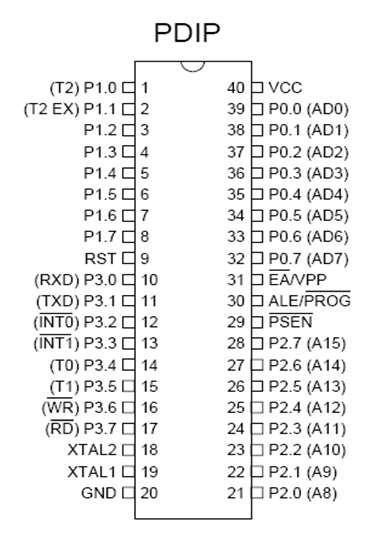
Fig no 5.2.5 :Pin diagram
5.2.5.1 Pin Description
VCC: Supply voltage.
GND: Ground.
Port 0
Port 0 is an 8-bit open drain bi-directional I/O port. As an output port, each pin can sink eight TTL inputs. When 1s are written to port 0 pins, the pins can be used as high impedance inputs. Port 0 can also be configured to be the multiplexed low order
Address/data bus during accesses to external program and data memory. In this mode, P0 has internal pull ups. Port 0 also receives the code bytes during Flash programming and outputs the code bytes during program verification. External pull ups are required during program verification.
Port 1
Port 1 is an 8-bit bi-directional I/O port with internal pull ups. The Port 1 output buffers can sink/source four TTL inputs. When 1s are written to Port 1 pins, they are pulled high by the internal pull ups and can be used as inputs. As inputs, Port 1 pins that are externally being pulled low will source current (IIL) because of the internal pull ups.
In addition, P1.0 and P1.1 can be configured to be the timer/counter 2 external count input (P1.0/T2) and the timer/counter 2 trigger input (P1.1/T2EX), respectively. Port 1 also receives the low-order address bytes during flash programming and verification.
Port 2
Port 2 is an 8-bit bi-directional I/O port with internal pull ups. The Port 2 output buffers can sink/source four TTL inputs. When 1s are written to Port 2 pins, they are pulled high by the internal pull ups and can be used as inputs. As inputs, Port 2 pins that are externally being pulled low will source current (IIL) because of the internal pull ups.
Port 2 emits the high-order address byte during fetches from external program memory and during accesses to external data memory that use 16-bit addresses (MOVX @DPTR). In this application, Port 2 uses strong internal pull ups when emitting 1s. During accesses to external data memory that use 8-bit addresses (MOVX @ RI), Port 2 emits the contents of the P2 Special Function Register.
Port 3
Port 3 is an 8-bit bi-directional I/O port with internal pull ups. The Port 3 output buffers can sink/source four TTL inputs. When 1s are written to Port 3 pins, they are pulled high by the internal pull ups and can be used as inputs. As inputs, Port 3 pins that are externally being pulled low will source current (IIL) because of the pull ups. Port 3 also serves the functions of various special features of the AT89C51.Port 3 also receives some control signals for Flash programming and verification.
RST
Reset input. A high on this pin for two machine cycles while the oscillator is running resets the device.
ALE/PROG
Address Latch Enable is an output pulse for latching the low byte of the address during accesses to external memory.
This pin is also the program pulse input (PROG) during Flash programming. In normal operation, ALE is emitted at a constant rate of 1/6 the oscillator frequency and may be used for external timing or clocking purposes. Note, however, that one ALE pulse is skipped during each access to external data memory.
PSEN
Program Store Enable is the read strobe to external program memory. When the AT89C52 is executing code from external program memory, PSEN is activated twice each machine cycle, except that two PSEN activations are skipped during each access to external data memory.
EA/VPP
External Access Enable. EA must be strapped to GND in order to enable the device to fetch code from external program memory locations starting at 0000H up to FFFFH. Note, however, that if lock bit 1 is programmed, EA will be internally latched on reset. EA should be strapped to VCC for internal program executions. This pin also receives the 12-volt programming enable voltage(VPP) during Flash programming when 12-volt programming is selected.
XTAL1
Input to the inverting oscillator amplifier and input to the internal clock operating circuit.
XTAL2
Output from the inverting oscillator amplifier.
5.2.6 ANALOG TO DIGITAL CONVERTER
FEATURES
· Single power supply
· Operating supply voltage 2.5 V to 6 V
· Low standby current
· Serial input/output via I2C-bus
· Address by 3 hardware address pins
· Sampling rate given by I2C-bus speed
· 4 analog inputs programmable as single-ended or differential inputs
· Auto-incremented channel selection
· Analog voltage range from VSS to VDD
· On-chip track and hold circuit
· 8-bit successive approximation A/D conversion
· Multiplying DAC with one analog output.
5.2.6.1 GENERAL DESCRIPTION
The PCF8591 is a single-chip, single-supply low power 8-bit CMOS data acquisition device with four analog inputs, one analog output and a serial I2C-bus interface .Three address pins A0, A1 and A2 are used for programming the hardware address, allowing the use of up to eight devices connected to the I2C-bus without additional hardware. Address, control and data to and from the device are transferred serially via the two-line bidirectional I2C-bus.The functions of the device include analog input multiplexing, on-chip track and hold function, 8-bit analog-to-digital conversion and an 8-bit digital-to-analog conversion. The maximum conversion rate is given by the maximum speed of the I2C-bus.
5.2.6.2 BLOCK DIAGRAM
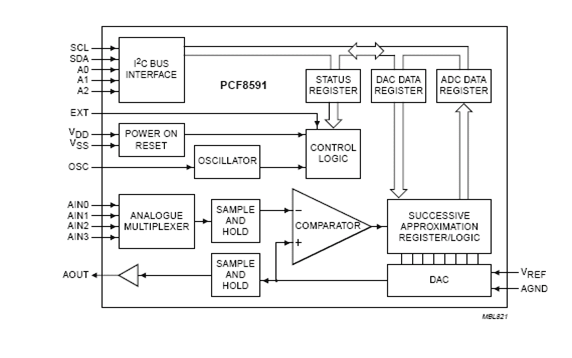 Fig no 5.2.6.2 : ADC
5.2.6.3 FUNCTIONAL DESCRIPTION
ADDRESSING
Each PCF8591 device in an I2C-bus system is activated by sending a valid address to the device. The address consists of a fixed part and a programmable part. The programmable part must be set according to the address pins A0, A1 and A2. The address always has to be sent as the first byte after the start condition in the I2C-bus protocol. The last bit of the address byte is the read/write-bit which sets the direction of the following data transfer.
CONTROL BYTE
The second byte sent to a PCF8591 device will be stored in its control register and is required to control the device function. The upper nibble of the control register is used for enabling the analog output. The lower nibble selects one of the analog input channels defined by the upper nibble. If the auto-increment mode is desired in applications where the internal oscillator is used, the analog output enable flag in the control byte (bit 6) should be set.
After a Power-on reset condition all bits of the control register are reset to logic 0. The D/A converter and the oscillator are disabled for power saving. The analog output is switched to a high-impedance state.
REFERENCE VOLTAGE
For the D/A and A/D conversioneither a stable external voltage reference or the supply voltage has to be applied to the resistor divider chain (pins VREF and AGND).The AGND pin has to be connected to the system analog ground and may have a DC off-set with reference to VSS.A low frequency may be applied to the VREF and AGND pins. This allows the use of the D/A converter as a one-quadrant multiplier. The A/D converter may also be used as a one or two quadrant analog divider. The analog input voltage is divided by the reference voltage. The result is converted to a binary code. In this application the user has to keep the reference voltage stable during the conversion cycle.
OSCILLATOR
An on-chip oscillator generates the clock signal required for the A/D conversion cycle and for refreshing the auto-zeroed buffer amplifier. When using this oscillator the EXT pin has to be connected to VSS. At the OSC pin the oscillator frequency is available. If the EXT pin is connected to VDD the oscillator output OSC is switched to a high-impedance state allowing the user to feed an external clock signal to OSC.
5.2.7 CHARACTERISTICS OF THE I²C-BUS
The I2C-bus is for bidirectional, two-line communication between different ICs or modules. The two lines are SDA and SCL. Both lines must be connected to a positive supply via a pull-up resistor. Data transfer may be initiated only when the bus is not busy.
5.2.7.1 I²C-BUS PROTOCAL
After a start condition a valid hardware address has to be sent to a PCF8591 device. The read/write bit defines the direction of the following single or multiple byte data transfer. For the format and the timing of the start condition (S), the stop condition (P) and the acknowledge bit (A) refer to the I2C-bus characteristics. In the write mode a data transfer is terminated by sending either a stop condition or the start condition of the next data transfer.
PIN DIAGRAM 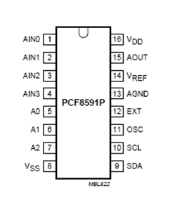

Fig no 5.2.7.1: pin diagram of PCF8591P
PIN DESCRIPTION
The PCF 8591 is a serial ADC, which is a 16 pin IC.
ANALOG INPUT
The ADC PCF 8591 has four analog inputs namely,
· AIN0 Analog input 0
· AIN1 Analog input 1
· AIN2 Analog input 2
· AIN3 Analog input 3
5.2.8 HARDWARE ADDRESS
The ADC uses A0, A1 and A2 that is pin 5, 6 and 7 are used to address the device from 000 to 111 (0 to 7). Totally eight ADC’s can be connected in the 2 pins.
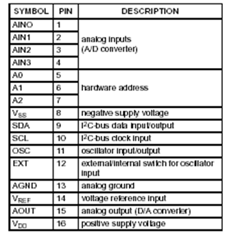 Table 5.2.8 : Hardware Address
PIN DETAILS
Vss:
The pin number 8 is given as Vss. The Vss is the negative supply given to the ADC PCF 8591.
SDA:
The SDA is Serial Data, which is used to transfer the digital data to the micro controller or to receive the digital data when it is used as ADC and DAC respectively.
SCL:
The SCL is the Serial Clock, which transfers the clock signal to the micro controller serially. Pin number 10 is used as SCL.
OSC:
Pin 11 is OSC, is the oscillator in which the clock signal can be given as input or taken as output.
EXT:
The EXT is a switch to say whether the oscillator is internal or external oscillator, which is given by pin number 12.
AGND:
Pin number 13 is given as Analog ground, which is used when the PCF act as DAC.
VREF:
The voltage range of the ADC is varied according to the VREF. If the VREF is 2.5, the range is 0 to 5volt. Pin 14 is VREF.
AOUT:
This pin is used when the PCF 8591 is used as DAC.
VDD:
The VDD is used as the positive supply, which is given as 5 volts.
5.2.8.1 APPLICATIONS
- Closed loop control systems
- Low power converter for remote data acquisition
- Battery operated equipment
- Acquisition of analog values in automotive, audio and TV applications.
6. SCADA
SCADA stands for supervisory control and data acquisition. It generally refers to an industrial control system: a computer system monitoring and controlling a process. The process can be industrial, infrastructure or facility-based as described below:
- Industrial processes include those of manufacturing, production, power generation, fabrication, and refining, and may run in continuous, batch, repetitive, or discrete modes.
- Infrastructure processes may be public or private, and include water treatment and distribution, wastewater collection and treatment, oil and gas pipelines, electrical power transmission and distribution, civil defense siren systems, and large communication systems.
- Facility processes occur both in public facilities and private ones, including buildings, airports, ships, and space stations. They monitor and control HVAC, access, and energy consumption.
6.1 Common system components
SCADA Systems are usually consists of the following subsystems:
- A Human-Machine Interface or HMI is the apparatus which presents process data to a human operator, and through this, the human operator monitors and controls the process.
- A supervisory (computer) system, gathering (acquiring) data on the process and sending commands (control) to the process.
- Remote Terminal Units (RTUs) connecting to sensors in the process, converting sensor signals to digital data and sending digital data to the supervisory system.
- Programmable Logic Controller (PLCs) used as field devices because they are more economical, versatile, flexible, and configurable than special-purpose RTUs.
- Communication infrastructure connecting the supervisory system to the Remote Terminal Units.
6.2 Supervision vs control
There is, in several industries, considerable confusion over the differences between SCADA systems and Distributed control systems (DCS). Generally speaking, a SCADA system usually refers to a system that coordinates, but does not control processes in real time. The discussion on real-time control is muddied somewhat by newer telecommunications technology, enabling reliable, low latency, high speed communications over wide areas. Most differences between SCADA and DCS are culturally determined and can usually be ignored. As communication infrastructures with higher capacity become available, the difference between SCADA and DCS will fade.
6.3 SYSTEMS CONCEPTS
The term SCADA usually refers to centralized systems which monitor and control entire sites, or complexes of systems spread out over large areas (anything between an industrial plant and a country). Most control actions are performed automatically by Remote Terminal Units (“RTUs”) or by Programmable Logic Controllers (“PLCs”). Host control functions are usually restricted to basic overriding or supervisory level intervention. For example, a PLC may control the flow of cooling water through part of an industrial process, but the SCADA system may allow operators to change the set points for the flow, and enable alarm conditions, such as loss of flow and high temperature, to be displayed and recorded. The feedback control loop passes through the RTU or PLC, while the SCADA system monitors the overall performance of the loop.
Data acquisition begins at the RTU or PLC level and includes meter readings and equipment status reports that are communicated to SCADA as required. Data is then compiled and formatted in such a way that a control room operator using the HMI can make supervisory decisions to adjust or override normal RTU (PLC) controls. Data may also be fed to a Historian, often built on a commodity Database Management System, to allow trending and other analytical auditing.
SCADA systems typically implement a distributed database, commonly referred to as a tag database, which contains data elements called tags orpoints. A point represents a single input or output value monitored or controlled by the system. Points can be either “hard” or “soft”. A hard point represents an actual input or output within the system, while a soft point results from logic and math operations applied to other points. (Most implementations conceptually remove the distinction by making every property a “soft” point expression, which may, in the simplest case, equal a single hard point.)
Points are normally stored as value-timestamp pairs: a value, and the timestamp when it was recorded or calculated. A series of value-timestamp pairs gives the history of that point. It’s also common to store additional metadata with tags, such as the path to a field device or PLC register, design time comments, and alarm information.
6.4 Human Machine Interface 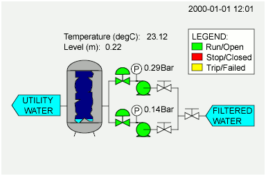

Fig no 6.4 :Human machine interface
A Human-Machine Interface or HMI is the apparatus which presents process data to a human operator, and through which the human operator controls the process.
An HMI is usually linked to the SCADA system’s databases and software programs, to provide trending, diagnostic data, and management information such as scheduled maintenance procedures, logistic information, detailed schematics for a particular sensor or machine, and expert-system troubleshooting guides. The HMI system usually presents the information to the operating personnel graphically, in the form of a mimic diagram. This means that the operator can see a schematic representation of the plant being controlled. For example, a picture of a pump connected to a pipe can show the operator that the pump is running and how much fluid it is pumping through the pipe at the moment. The operator can then switch the pump off. The HMI software will show the flow rate of the fluid in the pipe decrease in real time. Mimic diagrams may consist of line graphics and schematic symbols to represent process elements, or may consist of digital photographs of the process equipment overlain with animated symbols
The HMI package for the SCADA system typically includes a drawing program that the operators or system maintenance personnel use to change the way these points are represented in the interface. These representations can be as simple as an on-screen traffic light, which represents the state of an actual traffic light in the field, or as complex as a multi-projector display representing the position of all of the elevators in a skyscraper or all of the trains on a railway.
An important part of most SCADA implementations are alarms. An alarm is a digital status point that has either the value NORMAL or ALARM. Alarms can be created in such a way that when their requirements are met, they are activated. An example of an alarm is the “fuel tank empty” light in a car. The SCADA operator’s attention is drawn to the part of the system requiring attention by the alarm. Emails and text messages are often sent along with an alarm activation alerting managers along with the SCADA operator.
6.4.1 Hardware solutions
SCADA solutions often have Distributed Control System (DCS) components. Use of “smart” RTUs or PLCs, which are capable of autonomously executing simple logic processes without involving the master computer, is increasing. A functional block programming language, IEC 61131-3 (Ladder Logic), is frequently used to create programs which run on these RTUs and PLCs. Unlike a procedural language such as the C programming language or FORTRAN, IEC 61131-3 has minimal training requirements by virtue of resembling historic physical control arrays. This allows SCADA system engineers to perform both the design and implementation of a program to be executed on an RTU or PLC. A Programmable automation controller (PAC) is a compact controller that combines the features and capabilities of a PC-based control system with that of a typical PLC. PACs are deployed in SCADA systems to provide RTU and PLC functions. In many electrical substation SCADA applications, “distributed RTUs” use information processors or station computers to communicate with protective relays, PACS, and other devices for I/O, and communicate with the SCADA master in lieu of a traditional RTU.
Since about 1998, virtually all major PLC manufacturers have offered integrated HMI/SCADA systems, many of them using open and non-proprietary communications protocols. Numerous specialized third-party HMI/SCADA packages, offering built-in compatibility with most major PLCs, have also entered the market, allowing mechanical engineers, electrical engineers and technicians to configure HMIs themselves, without the need for a custom-made program written by a software developer.
Remote Terminal Unit (RTU)
The RTU connects to physical equipment. Typically, an RTU converts the electrical signals from the equipment to digital values such as the open/closed status from a switch or a valve, or measurements such as pressure, flow, voltage or current. By converting and sending these electrical signals out to equipment the RTU can control equipment, such as opening or closing a switch or a valve, or setting the speed of a pump.
6.4.2 Supervisory Station
The term “Supervisory Station” refers to the servers and software responsible for communicating with the field equipment (RTUs, PLCs, etc), and then to the HMI software running on workstations in the control room, or elsewhere. In smaller SCADA systems, the master station may be composed of a single PC. In larger SCADA systems, the master station may include multiple servers, distributed software applications, and disaster recovery sites. To increase the integrity of the system the multiple servers will often be configured in a dual-redundant or hot-standby formation providing continuous control and monitoring in the event of a server failure. Initially, more “open” platforms such as Linux were not as widely used due to the highly dynamic development environment and because a SCADA customer that was able to afford the field hardware and devices to be controlled could usually also purchase UNIX or OpenVMS licenses. Today, all major operating systems are used for both master station servers and HMI workstations.
6.4.2.1 Operational philosophy
For some installations, the costs that would result from the control system failing are extremely high. Possibly even lives could be lost. Hardware for some SCADA systems is ruggedized to withstand temperature, vibration, and voltage extremes, but in most critical installations reliability is enhanced by having redundant hardware and communications channels, up to the point of having multiple fully equipped control centres. A failing part can be quickly identified and its functionality automatically taken over by backup hardware. A failed part can often be replaced without interrupting the process. The reliability of such systems can be calculated statistically and is stated as the mean time to failure, which is a variant of mean time between failures. The calculated mean time to failure of such high reliability systems can be on the order of centuries.
6.5 COMMUNICATION INFRASTRUCTURE AND METHODS
SCADA systems have traditionally used combinations of radio and direct serial or modem connections to meet communication requirements, although Ethernet and IP over SONET / SDH is also frequently used at large sites such as railways and power stations. The remote management or monitoring function of a SCADA system is often referred to as telemetry. This has also come under threat with some customers wanting SCADA data to travel over their pre-established corporate networks or to share the network with other applications. The legacy of the early low-bandwidth protocols remains, though. SCADA protocols are designed to be very compact and many are designed to send information to the master station only when the master station polls the RTU. Typical legacy SCADA protocols include Modbus RTU, RP-570, Profibus and Conitel. These communication protocols are all SCADA-vendor specific but are widely adopted and used. Standard protocols are IEC 60870-5-101 or 104, IEC 61850 and DNP3. These communication protocols are standardized and recognized by all major SCADA vendors. Many of these protocols now contain extensions to operate over TCP/IP. It is good security engineering practice to avoid connecting SCADA systems to the Internet so the attack surface is reduced.
RTUs and other automatic controller devices were being developed before the advent of industry wide standards for interoperability. The result is that developers and their management created a multitude of control protocols. Among the larger vendors, there was also the incentive to create their own protocol to “lock in” their customer base. A list of automation protocols is being compiled here. Recently, OLE for Process Control (OPC) has become a widely accepted solution for intercommunicating different hardware and software, allowing communication even between devices originally not intended to be part of an industrial network
7. ETHERNET
7.1 INTRODUCTION TO ETHERNET
TCP/IP (Transmission Control Protocol/Internet Protocol) is a set of protocols independent of the physical medium used to transmit data, but most data transmission for Internet communication begins and ends with Ethernet frames. The Ethernet can use either a bus or star topology. A bus topology attaches all devices in sequence on a single cable. In a star topology all devices are wired directly to a central hub. 10Base-T uses a combination called a star-shaped bus topology because while the attached devices can share all data coming in on the cable, the actual wiring is in a star shape. The access method used by the Ethernet is called Carrier Sense Multiple Access with Collision Detect (CSMA/CD). This is a contention protocol, meaning it is a set of rules to follow when there is competition for shared resources.
ETHERNET ADDRESS
All Ethernet interfaces have a unique 48-bit address that is supplied by the manufacturer. It is called the Ethernet address (also known as the MAC address, for Media Access Control).
PHYSICAL CONNECTIONS
An Ethernet module provides a 10 Mbps/100Mbps Ethernet connection. This Module is used on our Controller boards. The corresponding port can be connected directly to an Ethernet network. By using hubs and routers, a network can include a large number of computers. A network might include all the computers in a particular building. A local network can be connected to the Internet by means of a gateway. The gateway is a computer that is connected both to the local network and to the Internet. Data that must be sent out over the Internet are sent to the local network interface of the gateway, and then the gateway sends them on to the Internet for routing to some other computer in the world. Data coming in from the Internet are directed to the gateway, which then sends them to the correct recipient on the local network.
CABLES
Ethernet cables are similar to U.S. telephone plug cables, except they have eight connectors. For our purposes, there are two types of cables—crossover and straight-through. In most instances, the straight through cables are used. It is necessary to use a crossover cable when two computers are connected directly without a hub (for example, if you want to connect your PC’s Ethernet directly to the TCP/IP Controller Board.) Some hubs have one input that can accept either a straight through or crossover cable depending on the position of a switch. In this case make sure that the switch position and cable type agree.
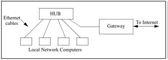 Fig no 7.1: Ethernet Network
FRAMES
Bits flowing across the Ethernet are grouped into structures called frames. A frame must be between 46 and 1500 bytes in size. An Ethernet frame has four parts: 1. A Preamble of 8 bytes that helps synchronize the circuitry, thus allowing small bit rate differences between sender and receiver. 2. A Header of 14 bytes that contains a 6 byte destination address, 6 byte source address and a 2 byte type field. 3. A Data area of variable length that, along with the header, is passed to the IP layer (aka. the Network layer). 4. A Trailer of 4 bytes that contains a CRC to guard against corrupted frames. If the destination address is all 1 bits, it defines a broadcast frame and all systems on the local network process the frame. There are also multicast frames. A subset of systems can form a “multicast” group that has an address that does not match any other system on the network. All systems in a particular subset process a packet with a destination address that matches their subset. A system can belong to any number of subsets.
A system may put its interface(s) into promiscuous mode and process all frames sent across its Ethernet. This is known as “sniffing the ether.” It is used for network debugging and spying.
COLLISIONS
In star-shaped bus topology, all systems have access to the network at any time. Before sending data, a system must determine if the network is free or if it is already sending a frame. If a frame is already being sent, a system will wait. Two systems can “listen” on the network and “hear” silence and then proceed to send data at the same time This is called a collision. Ethernet hardware has collision detection sensors to take care of this problem. This is the Collision Detect (CD) part of CSMA/CD. The colliding data is ignored, and the systems involved will wait a random amount of time before resending their data.
NETWORKING CONCEPTS
A network is a system of hardware and software, put together for the purpose of communication and resource sharing. A network includes transmission hardware, devices to interconnect transmission media and to control transmissions, and software to decode and format data, as well as to detect and correct problems. There are several types of networks in use today. This chapter will focus on three of them:
• LAN – Local Area Network
• WAN – Wide Area Network
• VPN – Virtual Private Network
LAN
The most widely deployed type of network; LANs were designed as an alternative to the more expensive point-to-point connection. A LAN has high throughput for relatively low cost. LANs often rely on shared media, usually a cable, for connecting many computers. This reduces cost. The computers take turns using the cable to send data.
REPEATERS AND BRIDGES
LANs typically connect computers located in close physical proximity, i.e., all the computers in a building. Repeaters are used to join network segments when the distance spanned causes electrical signals to weaken. Repeaters are basically amplifiers that work at the bit level; they do not actively modify data that is amplified and sent to the next segment. Like repeaters, bridges are used to connect two LANs together. Unlike repeaters, bridges work at the frame level. This is useful, allowing bridges to detect and discard corrupted frames. They can also perform frame filtering, only forwarding a frame when necessary. Both of these capabilities decrease network congestion. Bridged LANs can span arbitrary distances when using a satellite channel for the bridge. The resulting network is still considered a LAN and not a WAN.
WAN
To be considered a WAN, a network must be able to connect an arbitrary number of sites across an arbitrary distance, with an arbitrary number of computers at each site. In addition, it must have reasonable performance (no long delays) and allow all of the computers connected to it to communicate simultaneously. This is accomplished with packet switches.
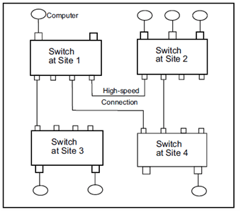
Fig no 7.1.1 : WAN with 4 Switches
PACKET SWITCHES
Packet switches are small computers with CPUs, memory and I/O devices. They move complete packets, using a technique called Store and Forward. An incoming packet is stored in a memory buffer and the CPU is interrupted. The processor examines the packet and forwards it to the appropriate place. This strategy allows the switch to accept multiple packets simultaneously. As the figure above illustrates, WANs currently do not need to be symmetric.
FORWARDING A PACKET
A data structure contains the information that tells the switch where to send the packet next. This is called a routing table. The destination address in the packet header determines the routing table entry that is used to forward the packet. It could be forwarded to a computer attached to the switch that is examining the packet or it could be to another switch in the WAN.
VPN
VPNs are built on top of a publicly-accessible infrastructure, such as the Internet or the public telephone network. They use some form of encryption and have strong user authentication. Essentially a VPN is a form of WAN; the difference is their ability to use public networks rather than private leased lines. A VPN supports the same intranet services as a traditional WAN, but also supports remote access service. This is good for telecommuting, as leased lines don’t usually extend to private homes and travel destinations. A remote VPN user can connect via an Internet Service Provider (ISP) in the usual way. This eliminates long-distance charges. The user can then initiate a tunnel request to the destination server. The server authenticates the user and creates the other end of the tunnel. VPN software encrypts the data, packages it in an IP packet (for compatibility with the Internet) and sends it through the tunnel, where it is decrypted at the other end. There are several tunneling protocols available: IP security (IP sec), Point-to-Point Tunneling Protocol (PPTP) and Layer 2 Tunneling Protocol (L2TP).
NETWORK DEVICES
Some network devices (repeaters, bridges and switches) were discussed in the previous sections. These are all dedicated hardware devices. Network devices can also be non-dedicated systems running network software.
ROUTERS
A router is a hardware device that connects two or more networks. Routers are the primary backbone device of the Internet, connecting different network technologies into a seamless whole. Each router is assigned two or more IP addresses because each IP address contains a prefix that specifies a physical network. Before a packet is passed to the routing software, it is examined. If it is corrupted, it is discarded. If it is not corrupted, a routing table is consulted to determine where to send it next. By default, routers do not propagate broadcast packets (see “Directed Broadcast Address” on page —). A router can be configured to pass certain types of broadcasts.
FIREWALLS
A firewall is a computer, router, or some other communications device that controls data flow between networks. Generally, a firewall is a first-line defense against attacks from the outside world. A firewall can be hardware-based or software-based. A hardware-based firewall is a special router with additional filter and management capabilities. A software-based firewall runs on top of the operating system and turns a PC into a firewall. Conceptually, firewalls can be categorized as Network layer (aka Data Link layer) or Application layer. Network layer firewalls tend to be very fast. They control traffic based on the source and destination addresses and port numbers, using this information to decide whether to pass the data on or discard it. Application layer firewalls do not allow traffic to flow directly between networks. They are typically hosts running proxy servers. Proxy servers can implement protocol specific security because they understand the application protocol being used. For instance, an application layer firewall can be configured to allow only e-mail into and out of the local network it protects.
GATEWAYS
A gateway performs routing functions. The term default gateway is used to identify the router that connects a LAN to an internet. A gateway can do more than a router; it also performs protocol conversions from one network to another.
7.2 NETWORK ARCHITECTURE
There are two network architectures widely used today: peer-to-peer and client/server. In peer-to-peer networks each workstation has the same capabilities and responsibilities. These networks are usually less expensive and simpler to design than client/server networks, but they do not offer the same performance with heavy traffic.
CLIENT/SERVER NETWORKS
The client/server paradigm requires some computers to be dedicated to serving other computers. A server application waits for a client application to initiate contact.
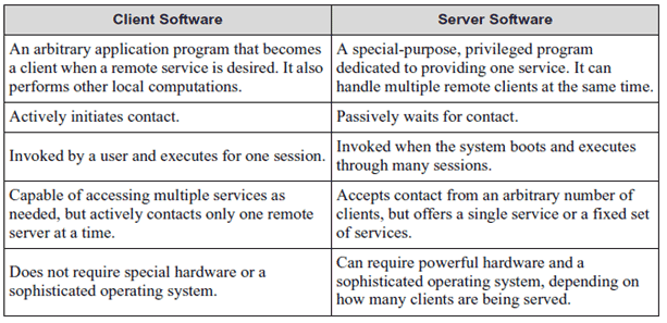
Table 7.2: Summary of Differences between Client and Server Software
PORT NUMBERS
Port numbers are the mechanism for identifying particular client and server applications. Servers select a port to wait for a connection. Most services have well-known port numbers. For example, HTTP uses port 80. When a web browser (the client) requests a web page it specifies port 80 when contacting the server. Clients usually have ephemeral port numbers since they exist only as long as the session lasts. Some of the common well-known TCP port numbers are listed in the table below.
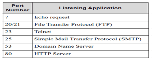 Table 7.2.1: Port number mechanism
NETWORKING PROTOCOLS
Computers on a network communicate in agreed upon ways called protocols. The complexity of networking protocol software calls for the problem to be divided into smaller pieces. A layering model aids this division and provides the conceptual basis for understanding how software protocols together with hardware devices provide a powerful communication system.
7.3 LAYERING MODELS
In the early days of networking, before the rise of the ubiquitous Internet, the International Organization for Standardization (ISO) developed a layering model whose terminology persists today.
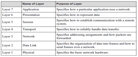
Table 7.3: ISO 7-Layer Reference Model The 7-layer model has been
revised to the 5-layer TCP/IP reference model to meet the current needs of protocol designers.

Table 7.3.1: TCP/IP 5-Layer Reference Model
8. TCP/IP Protocol Stack
TCP/IP is the protocol suite upon which all Internet communication is based. Different vendors have developed other networking protocols, but even most network operating systems with their own protocols, such as Netware, support TCP/IP. It has become the de facto standard. Protocols are sometimes referred to as protocol stacks or protocol suites. A protocol stack is an appropriate term because it indicates the layered approach used to design the networking software
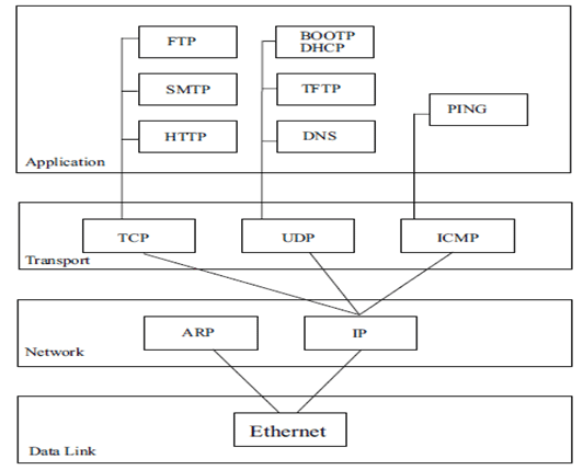
Fig no 8 : Flow of Data Between Two Computers Using TCP/IP Stacks
Each host or router in the internet must run a protocol stack. The details of the underlying physical connections are hidden by the software. The sending software at each layer communicates with the corresponding layer at the receiving side through information stored in headers. Each layer adds its header to the front of the message from the next higher layer. The header is removed by the corresponding layer on the receiving side.
8.1 TCP/IP Protocol
This chapter discusses the protocols available in the TCP/IP protocol suite. The following figure shows how they correspond to the 5-layer TCP/IP Reference Model. This is not a perfect one-to-one correspondence; for instance, Internet Protocol (IP) uses the Address Resolution Protocol (ARP), but is shown here at the same layer in the stack.
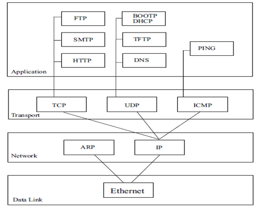
IP
IP provides communication between hosts on different kinds of networks (i.e., different data-link implementations such as Ethernet and Token Ring). It is a connectionless, unreliable packet delivery service. Connectionless means that there is no handshaking, each packet is independent of any other packet. It is unreliable because there is no guarantee that a packet gets delivered; higher-level protocols must deal with that.
IP Address
IP defines an addressing scheme that is independent of the underlying physical address (e.g, 48-bit MAC address). IP specifies a unique 32-bit number for each host on a network. This number is known as the Internet Protocol Address, the IP Address or the Internet Address. These terms are interchangeable. Each packet sent across the internet contains the IP address of the source of the packet and the IP address of its destination. For routing efficiency, the IP address is considered in two parts: the prefix which identifies the physical network, and the suffix which identifies a computer on the network. A unique prefix is needed for each network in an internet. For the global Internet, network numbers are obtained from Internet Service Providers (ISPs). ISPs coordinate with a central organization called the Internet Assigned Number Authority.
IP Address Classes
The first four bits of an IP address determine the class of the network. The class specifies how many of the remaining bits belong to the prefix (aka Network ID) and to the suffix (aka Host ID). The first three classes, A, B and C, are the primary network classes.

Table 8.1: IP Address Classes
When interacting with mere humans, software uses dotted decimal notation; each 8 bits is treated as an unsigned binary integer separated by periods. IP reserves host address 0 to denote a network. 140.211.0.0 denotes the network that was assigned the class B prefix 140.21.
8.2 Netmasks
Netmasks are used to identify which part of the address is the Network ID and which part is the Host ID. This is done by a logical bitwise-AND of the IP address and the netmask. For class A networks the netmask is always 255.0.0.0; for class B networks it is 255.255.0.0 and for class C networks the netmask is 255.255.255.0.
Subnet Address
All hosts are required to support subnet addressing. While the IP address classes are the convention, IP addresses are typically subnetted to smaller address sets that do not match the class system. The suffix bits are divided into a subnet ID and a host ID. This makes sense for class A and B networks, since no one attaches as many hosts to these networks as is allowed. Whether to subnet and how many bits to use for the subnet ID is determined by the local network administrator of each network. If subnetting is used, then the netmask will have to reflect this fact. On a class B network with subnetting, the netmask would not be 255.255.0.0. The bits of the Host ID that were used for the subnet would need to be set in the netmask.
Directed Broadcast Address
IP defines a directed broadcast address for each physical network as all ones in the host ID part of the address. The network ID and the subnet ID must be valid network and subnet values. When a packet is sent to a network’s broadcast address, a single copy travels to the network, and then the packet is sent to every host on that network or subnetwork.
Limited Broadcast Address
If the IP address is all ones (255.255.255.255), this is a limited broadcast address; the packet is addressed to all hosts on the current (sub) network. A router will not forward this type of broadcast to other (sub) networks.
8.2.1 IP Routing
Each IP datagram travels from its source to its destination by means of routers. All hosts and routers on an internet contain IP protocol software and use a routing table to determine where to send a packet next. The destination IP address in the IP header contains the ultimate destination of the IP datagram, but it might go through several other IP addresses (routers) before reaching that destination. Routing table entries are created when TCP/IP initializes. The entries can be updated manually by a network administrator or automatically by employing a routing protocol such as Routing Information Protocol (RIP). Routing table entries provide needed information to each local host regarding how to communicate with remote networks and hosts. When IP receives a packet from a higher-level protocol, like TCP or UDP, the routing table is searched for the route that is the closest match to the destination IP address. The most specific to the least specific route is in the following order:
• A route that matches the destination IP address (host route).
• A route that matches the network ID of the destination IP address (network route).
• The default route.
If a matching route is not found, IP discards the datagram. IP provides several other services:
• Fragmentation: IP packets may be divided into smaller packets. This permits a large packet to travel across a network which only accepts smaller packets. IP fragments and reassembles packets transparent to the higher layers.
• Timeouts: Each IP packet has a Time To Live (TTL) field, that is decremented every time a packet moves through a router. If TTL reaches zero, the packet is discarded.
• Options: IP allows a packet’s sender to set requirements on the path the packet takes through the network (source route); the route taken by a packet may be traced (record route) and packets may be labeled with security features.
8.2.2 ARP
The Address Resolution Protocol is used to translate virtual addresses to physical ones. The network hardware does not understand the software-maintained IP addresses. IP uses ARP to translate the 32-bit IP address to a physical address that matches the addressing scheme of the underlying hardware (for Ethernet, the 48-bit MAC address). There are three general addressing strategies:
1. Table Lookup
2. Translation performed by a mathematical function
3. Message exchange
TCP/IP can use any of the three. ARP employs the third strategy, message exchange. ARP defines a request and a response. A request message is placed in a hardware frame (e.g., an Ethernet frame), and broadcast to all computers on the network. Only the computer whose IP address matches the request sends a response.
8.3 The Transport Layer
There are two primary transport layer protocols: Transmission Control Protocol (TCP) and User Datagram Protocol (UDP). They provide end-to-end communication services for applications.
8.3.1 UDP
This is a minimal service over IP, adding only optional check summing of data and multiplexing by port number. UDP is often used by applications that need multicast or broadcast delivery, services not offered by TCP. Like IP, UDP is connectionless and works with datagrams.
8.3.2 TCP
TCP is a connection-oriented transport service; it provides end-to-end reliability, resequencing, and flow control. TCP enables two hosts to establish a connection and exchange streams of data, which are treated in bytes. The delivery of data in the proper order is guaranteed. TCP can detect errors or lost data and can trigger retransmission until the data is received, complete and without errors.
TCP Connection/Socket
A TCP connection is done with a 3-way handshake between a client and a server. The following is a simplified explanation of this process.
• The client asks for a connection by sending a TCP segment with the SYN control bit set.
• The server responds with its own SYN segment that includes identifying information that was sent by the client in the initial SYN segment.
• The client acknowledges the server’s SYN segment.
The connection is then established and is uniquely identified by a 4-tuple called a socket or socket pair: (Destination IP address, destination port number) (Source IP address, source port number) During the connection setup phase, these values are entered in a table and saved for the duration of the connection.
TCP Header
Every TCP segment has a header. The header comprises all necessary information for reliable, complete delivery of data. Among other things, such as IP addresses, the header contains the following fields:
Sequence Number – This 32-bit number contains either the sequence number of the first byte of data in this particular segment or the Initial Sequence Number (ISN) that identifies the first byte of data that will be sent for this particular connection. The ISN is sent during the connection setup phase by setting the SYN control bit. An ISN is chosen by both client and server. The first byte of data sent by either side will be identified by the sequence number ISN + 1 because the SYN control bit consumes a sequence number.
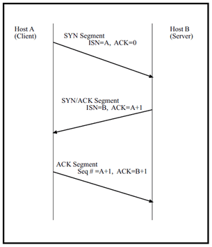 Figure 4.2 illustrates the three way handshake.
Fig no 8.3.2 : Synchronizing Sequence Numbers for TCP Connection. The sequence number is used to ensure the data is reassembled in the proper order before being passed to an application protocol.
Acknowledgement Number – This 32-bit number is the other host’s sequence number + 1 of the last successfully received byte of data. It is the sequence number of the next expected byte of data. This field is only valid when the ACK control bit is set. Since sending an ACK costs nothing, (because it and the Acknowledgement Number field are part of the header) the ACK control bit is always set after a connection has been established. The Acknowledgement Number ensures that the TCP segment arrived at its destination.
Control Bits – This 6-bit field comprises the following 1-bit flags (left to right): • URG – Makes the Urgent Pointer field significant. • ACK – Makes the Acknowledgement Number field significant. • PSH – The Push Function causes TCP to promptly deliver data. • RST – Reset the connection. • SYN – Synchronize sequence numbers. • FIN – No more data from sender, but can still receive data.
Window Size – This 16-bit number states how much data the receiving end of the TCP connection will allow. The sending end of the TCP connection must stop and wait for an acknowledgement after it has sent the amount of data allowed.
Checksum – This 16-bit number is the one’s complement of the one’s complement sum of all bytes in the TCP header, any data that is in the segment and part of the IP packet. A checksum can only detect some errors, not all, and cannot correct any.
ICMP – Internet Control Message Protocol is a set of messages that communicate errors and other conditions that require attention. ICMP messages, delivered in IP datagrams, are usually acted on by either TCP/IP or UDP. Some ICMP messages are returned to application protocols. A common use of ICMP is “pinging” a host. The Ping command (Packet INternet Groper) is a utility that determines whether a specific IP address is accessible. It sends an ICMP echo request and waits for a reply. Ping can be used to transmit a series of packets to measure average round-trip times and packet loss percentages.
8.4 The Application Layer
There are many applications available in the TCP/IP suite of protocols. Some of the most useful ones are for sending mail (SMTP), transferring files (FTP), and displaying web pages (HTTP Another important application layer protocol is the Domain Name System (DNS). Domain names are significant because they guide users to where they want to go on the Internet.
DNS
The Domain Name System is a distributed database of domain name and IP address bindings. A domain name is simply an alphanumeric character string separated into segments by periods. It represents a specific and unique place in the “domain name space.” DNS makes it possible for us to use identifiers such as google.com to refer to an IP address on the Internet. Name servers contain information on some segment of the DNS and make that information available to clients who are called resolvers.
9. PROGRAM
See the attachment.
10. CONCLUSION
We have gained a wonderful experience in NLC limited. We had a useful knowledge about our project.
The theory and concepts of generator cooling were extensively discussed. Based on this concept, a practical model for cooling of generator using Micro-controller is developed. The use of Microcontroller increases the reliability of the system. Time consumption is very less in this system. It also has added advantages like on-chip memory, easy service and very economical. Thus we conclude that the cooling of generators using our project is more advantageous than the existing system (i.e) the existing system which is manual is made automatic in our project. This system does a very essential work to cool the generators efficiently.
Future scope of this project is that it can be implemented by using Bluetooth or IR Rays.
Project Source Code
Circuit Diagrams
Project Datasheet
Filed Under: Electronic Projects



Questions related to this article?
👉Ask and discuss on Electro-Tech-Online.com and EDAboard.com forums.
Tell Us What You Think!!
You must be logged in to post a comment.