Sim900d gsm/gprs module works on AT command set. Almost every GSM chip by simcom works on AT command set. An external microcontroller is required to talk to sim900 gsm module. Sim900 communicates with external controller on UART protocol. In uart protocol only two pins are required to talk with external devices Tx(Transmit) and Rx(Receive). Both the devices must have one single uart port to talk with each other. Communication speed in uart protocol is termed as baud rate. We first have to set the baud rate speed of the modules who are going to communicate on uart protocol. Both the modules must be on the same speed for successful communication.
Arduino has a default uart port on its pins#0 and 1. So arduino can talk to devices which requires uart protocol for communication. Arduino Rx or pin#0 is tied to Tx of sim900 module and arduino Tx or pin#1 is tied with Rx of sim900 module for communication.
Coming to wards ‘AT’ command set. Their are numerous ‘AT’ commands if you go through the data sheet of sim900 gsm module. In this tutorial i will explain only the ones which are required to send an sms with gsm sim900 module. If you wan to learn all the commands go through the data sheet of sim900 module. AT commands which are required to send a text message/sms are listed below. .

MY diy arduino gsm module interface circuit
GSM Module sim900d with arduino uno-mega
First insert your sim in the sim900 module sim slot and be sure you have credit/balance in it for texting to other numbers. Connect Arduino uno Rx(Pin#0) to GSM module TX and TX(Pin#1) of Arduino uno to RX of sim900 GSM module.
Sim900 requires about 5 volts and 1 ampere of current while transmitting the sms/text message. We can not power the gsm module directly with the arduino 5v output. External dc adopter which can supply continuous 1 ampere of current at 5 volt is enough for the arduino and sim900 module power requirements. Note: If your GSM stops working and restarts it self when you send commands to it. It means your GSM needs more current. Try to power your circuit with high rating of source like on the right side i powered the diy circuit with 4.5 Ah 5v DC batter. |
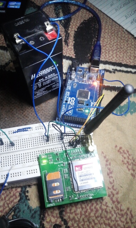
GSM sim900d with arduino mega and battery-circuit Diagram
|
|
One can use any sim900 gsm module by any vendor/manufacturer to interface it with arduino. The circuit connections will be same as given on the right hand side.
|
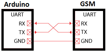
Arduino Gsm module Uart interface
|
Some keys present on sim900 gsm older modules
- Recall that sim900 accepts the cell number of the recipient enclosed in double quotations.
- To send the recipient cell number to sim900 gsm module using arduino ide we must put the \” in the code statement. If we do not put the \. Then arduino ide compiler identifies it as the arduino ide statement and executes it rather than sending it on uart to sim900 module. \” tells the arduino ide compiler that “ is data to be send out on uart.
At the end of the code i inserted a while(1) loop. While loop will hold the control for ever. It means our code will execute only once after power up and after than it stops.
I made arduino home security system using arduino gsm module, pir motion detector sensor and door contact sensor. Visit the diy project by clicking the below button.
Watch the project video Here… Sending text SMS through Arduino uno to remote cell Phone using Sim900d GSM module.
Filed Under: Arduino, Microcontroller Projects

Questions related to this article?
👉Ask and discuss on EDAboard.com and Electro-Tech-Online.com forums.
Tell Us What You Think!!
You must be logged in to post a comment.