Home appliances controlled by RF Remote control
Introduction:
When we were children, lot of time we played with TV remote. We change channels by pointing remote towards the TV. Sometimes we will try to change the channels by pointing TV remote in other direction. But it did not work. This is because TV remotes are Infrared remote control. Infrared remotes can be worked in line of sight only. We can’t control TV from other rooms. If we want to control TV from other rooms or if we want to switch ON/OFF light or fan then IR remote control cannot be used. For such application we have to replace IR technology with RF technology because RF remote controls can work without line of sight also.
The new thing in this project is, it controls different AC based home appliances using RF remote control. We can switch ON/OFF any home appliance like light, fan, bulb, heater etc from anywhere inside home.
Description:
In this project we are using only one transmitter (that works as remote control) and one receiver (that is connected with different AC loads) build using HT12E and HT12D. We can control four AC appliances (loads) which are connected to receiver using four switches which are connected to transmitter. In this circuit relays are used to switch AC loads ON/OFF.
So lets start making this interesting project but before that first collect all required components and other equipments.
Required components and equipments:
Sr. no. Name of component Required quantity
1 RF Tx module(434Mhz) 1
2 RF Rx module(434Mhz) 1
3 HT12E 1
4 HT12D 1
5 LED 1
6 Resistor – 100Ω (Quarter watt) 4
7 Resistor – 1MΩ (Quarter watt) 1
8 Resistor – 50KΩ (Quarter watt) 1
9 Transistor BC547 4
10 Resistor – 1KΩ (Quarter watt) 4
11 Battery – 9V 2
12 Single change over type relay 4
13 1N4007 diode 4
14 Light bulb 4
15 Push button switches 4
16 Bread board
17 connecting wires
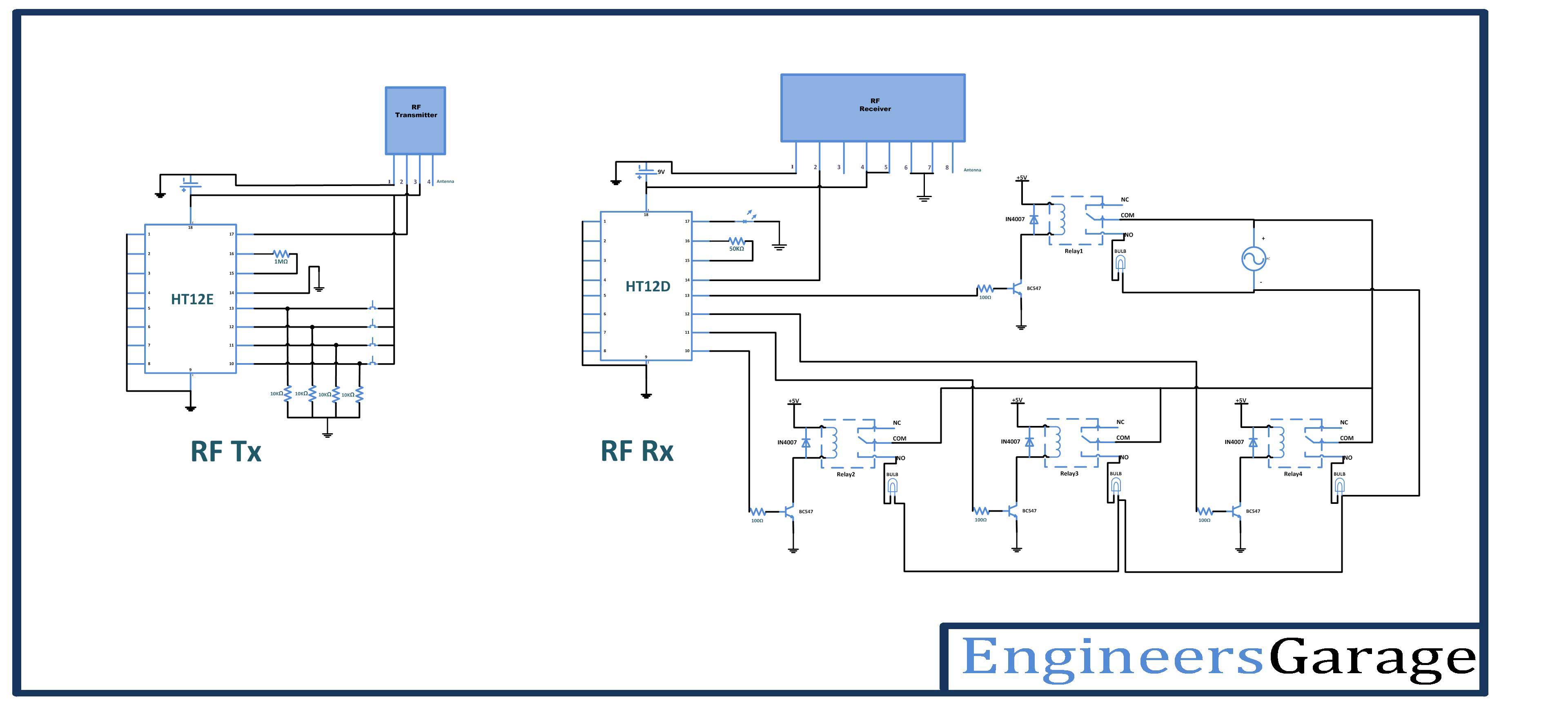
Circuit diagram:
To build above circuit follow the step by step procedure
Procedure:
Transmitter section:
Step1: connect the four push button switches to the data input pins (10,11,12,13) of HT12E, with pull down resistors of 1 KΩ.
Step2: connect 1MΩ resistor between 15 and 16 pins of HT12E.
Step3: connect 17 pin to the 2nd pin of RF transmitter, and 14 pin connect to the ground.
Step4: 1-8 pins of HT12E are address pins, all are connected to ground. Pin 18 is connected to Vcc and pin 9 is connected to ground.
Step5: Connect RF Tx module’s pin 1 to the ground, pin 3 to the Vcc and pin 4 to the antenna.
Receiver section:
Step1: connect pins 10,11,12,13 of decoder HT12D to base of four transistors (relay control circuits) through 330E resistor.
Step2: connect the transistor emitter directly to the ground and collector to the one coil terminal of relay
Step3: connect the diode between two coil terminals of relay in reverse bias configuration
Step4: connect the AC supply phase wire to every common (C) pin of realy, and connect NO pin to one terminal of BULB. Connect other terminal of bulb AC supply neutral wire.
Step5 : connect 50KΩ resistor between 15 and 16 pins of HT12D.
Step6: Connect pin 14 to the 2nd pin of RF Rx module, and connect pin 17 to the LED indicator (it will glow when signal is received)
Step7: 1-8 pins of HT12D are address pins, all are connected to ground Connect pin 18 to Vcc and pin 9 to ground.
Step8: Connect RF Rx module’s 1, 6, 7 pins to the ground, pins 4 & 5 to the Vcc and pin 8 to the antenna.
Working:
1. The HT12E encoder inputs are controlled by switches, this parallel data converted by encoder to the serial data and fed to transmitter input pin 2 from the encoder 17th pin.
2. Transmitted data is ASK modulated signal means the data present in variations of the amplitude. The receiver within the range can receive the ASK signal and generates serial data same as at transmitter and fed to 14th pin of decoder (HT12D).
3. This serial data is converted in to parallel data by the decoder and the parallel data output is available at 10,11,12,13 pins of decoder.
4. When at transmitter side any switch pressed, at receiver side that output goes high
5. Decoder output is given to the base of BC547 transistor through resistor (100ohms).
6. So when decoder output becomes high transistor conducts and it switches particular relay
7. As relay is switched the bulb gets AC supply and it turns ON
Pictures:


Thus we can control four different devices using four switches wirelessly using RF remote control.
Troubleshooting:
While dealing with relay, take care about some connections as here AC source also involed, so it is required to connect one freewheeling diode between relay coil terminals. This is required because when we apply a voltage to a coil is creates a magnetic field. When you remove the voltage the magnetic field collapses and creates a reverse polarity voltage and can be many times the value of the original applied voltage. This creates a transient voltage pulse that can damage other components in the circuit that are not rated for this polarity or the higher voltage created, things like semiconductors and caps have a maximum voltage limit and breakdown if exceeded. Having a reversed biased diode across the coil allows the diode to conduct for reverse polarity voltages and creates a ‘short circuit’ across the coil that allows the pulse to be dissipated in the resistance of the coil wiring.
When I am doing this project at starting I tried to control the relay without connecting transistor but I didn’t get output, but after connecting relay using a BC547 transistor it worked fine.
While running the circuit it is required to take following precautions
Precautions:
1. Address lines status (high/low) should be same at both transmitter and receiver.
2. At transmitter 14th pin of HT12E should be connect to ground or connect a switch between ground and the 14th pin to reset the encoder.
3. In the transmitter circuit the resistor connected between 15 and 16 pins of HT12E should be between 750MΩ to 1MΩ. And at receiver side the resistor connected between 15 and 16 pins of HT12D should be between 30KΩ to 50KΩ.
4. Incase if you want to use any other battery, checkout the data sheet of HT12E/HT12D first.
5. Take care of AC line connections with load and relay
Project Source Code
Circuit Diagrams
Filed Under: Electronic Projects

Questions related to this article?
👉Ask and discuss on Electro-Tech-Online.com and EDAboard.com forums.
Tell Us What You Think!!
You must be logged in to post a comment.