There’s a useful side effect to the way the LCD controller uses CG RAM. Normally, we define a pattern in CG RAM, and then print the character. But it is also possible to change the CG RAM for characters that are already on the screen, and their appearance will change (for more detail about CG RAM and LCD refer LCD custom character and LCD interfacing).
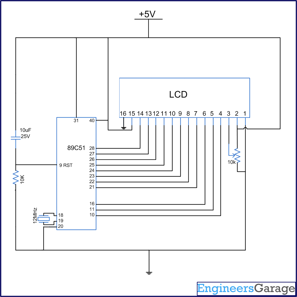
The connections in the circuit are as follow: the output of controller (from port P2) goes to data pins of LCD numbered 7-14. The control pins RS (pin4), R/W (pin5) and EN (pin6) are connected to the pins 0, 1 and 6 of port P3 (P3^0, P3^1 & P3^6, respectively).
Sample animation: A moving arrow continuously passing through hearts.
Before animation, the custom characters of heart, cutting heart, blank screen and arrow should be stored at different addresses. For more detail on creating custom characters refer LCD custom character.
In 1st step print an arrow and two hearts placed at some distance apart.
In 2nd step print blank screen, cutting heart and 2nd heart.
In 3rd step print blank screen, heart, arrow and 2nd heart.
In 4th step print blank screen, heart, blank screen, arrow and 2nd heart.
In 5th step print blank screen, heart, blank screen, blank screen and
cutting heart.
These steps can be repeated continuously to produce an animation.
Project Source Code
###
//Program to###
Circuit Diagrams
| Circuit-Diagram-of-Displaying-Custom-Animations-On-16×2-LCD-Using-8051-Microcontroller-AT89C51-On-Breadboard-1 |  |
Filed Under: Electronic Projects


Questions related to this article?
👉Ask and discuss on EDAboard.com and Electro-Tech-Online.com forums.
Tell Us What You Think!!
You must be logged in to post a comment.