The serial communication port is one of the communication medium available in almost all microcontrollers. It is the most effective communication method available with a microcontroller. The serial port of the microcontroller provides the easiest way by which the user and the microcontroller can write their data in the same medium and both can read each other’s data. When the serial port of the microcontroller is connected to the PC and the incoming and outgoing data is monitored using software and displayed in a window, it forms the simplest text user interface (TUI) setup for the microcontroller. Serial communication is a very useful debugging tool in the code development process. It can send back the run time status of the internal registers, value of the variables etc. When a given with a microcontroller a developer will first try to make the serial port up and working so that it can be used for debugging purpose for all the future projects.
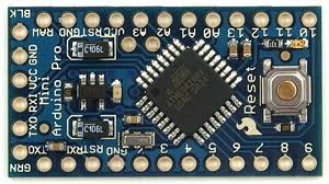
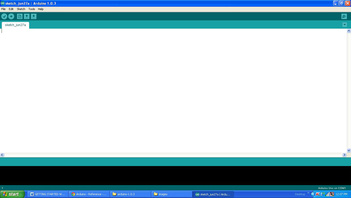
The arduino pro-mini board is used for a previous project on how to use the analog input and output of the arduino. The different values appear at the analog input and analog output of the arduino board will be monitored using the serial monitor tool in the arduino IDE version 1.0.3 for windows. The image of the arduino pro-mini board and the arduino IDE are shown below;

Fig. 2: Typical Arduino Pro-Mini Board

Fig. 3: Arduino IDE Software Window

It is assumed that the reader has gone through the project Getting started with Arduino and tried out the project on how to use the analog input and output of the arduino. This project also make use of the serial port accessing functions explained in the projects on how to receive and send serial data using arduino and how to do serial communication using arduino.
Serial.begin()
This function is used in the code to initialize the serial port with the baud rate 9600 which is given as the argument of the function and also with 8 bits of data frame, one start bit, one stop bit and no parity bits using the statement given below;
Serial.begin(9600);
Serial.print()
The Serial.print() function is used in the code to send the value to the serial port that has to be monitored. This function formats the value to ASCII characters so that it can be displayed in the serial monitor window. For example if the variable ‘var’ has a value 10, then it can be displayed on the serial port as 10 using the following statement
Serial.print(var);
In short the Serial.print() function actually ‘prints’ the value which is given as a parameter to it on the serial monitor.
Serial.println()
The function Serial.println() is also used in the same manner but to introduce a new line and carriage return after printing the value in the serial monitor. The values printed after the Serial.println() function will appear on the next line in the window.
analogRead()
This function is used to enable the built-in ADC of the arduino’s microcontroller which then converts the analog value appears in a particular pin to its 10 bit digital equivalent and then stores in the variable.
The above statement reads the value from the A0 and stores it in the variable ‘var’. The serial printing functions are then used to print the value of this variable in this particular project.
map()
The map() is a built-in function which can be used to map the value from one rage to another range. For example the ADC of the arduino generates 10 bit values but the PWM module of the arduino can produce 8 bit equivalent waveforms. If there is a requirement to directly write the analog input value to the analog output one can make use of the map() function as follows;
var = map(potvalue, 0, 1023, 0, 255);
The above statement will convert the value which is in the range of 0 to 1023 (the output of 10 bit ADC) into the range 0 to 255 (the input range of 8 bit PWM) and stores it in a variable ‘var’. The variable ‘var’ could be of the type integer or character.
This project also monitors the mapped variable’s value before using that variable to generate the analog voltage in an analog output pin.
analogWrite()
This function can write an analog value into an analog output pin mentioned in its argument to generate the equivalent voltage on that pin. For example one can make use of the analogWrite() function to generate a voltage equivalent of value 100 on an analog output pin 5 as shown below;
analogWrite (5, 100);
The above statement will actually write the value 100 to an 8 bit PWM module which will generate a corresponding width modulated waveform on the pin number 5 so as to generate the equivalent voltage on the device connected to that pin.
Once the coding is finished one can verify and upload the code to the arduino board as explained in the project how to get started with the arduino. The following section explains how to connect the arduino board with the serial monitor tool.
SERIAL MONITOR
The serial monitor tool can be selected from the same IDE which has been used for verifying and uploading the code. For any other serial monitor tool the IDE should be closed before connecting the arduino board and hence it is always an advantage to be having the serial monitor tool in the IDE itself. If any error has been noticed one can quickly change the code, upload it and check it again which speeds up the code development process.

Fig. 5: Serial Monitor Tool in IDE Window
As shown in the above image the serial monitor can be selected from the tools->serial monitor and for this particular project the display on the serial monitor appears as shown in the following image.

Fig. 6: Serial Debugger Demo
Project Source Code
###


/*============================ EG LABS ===================================//

 Demonstration on how to use serial monitor with an arduino board

 The circuit:

 * Potentiometer attached to analog input A0

 * one side pin (either one) to ground

 * the other side pin to +5V

 * LED anode (long leg) attached to digital output 5

 * LED cathode (short leg) attached to ground through a 1K resistor


//============================ EG LABS ===================================*/

const int analogInPin = A0;  // Analog input pin that the potentiometer is attached to

const int analogOutPin = 5;  // Analog output pin that the LED is attached to

int potvalue = 0;

int outputvalue=0;

void setup()

{

  // start serial port at 9600 bps

  Serial.begin(9600);

  // wait for a while till the serial port is ready

  delay(100);

  // send the initial data once //

  Serial.print('n');

  Serial.print("       EG LABS      ");

  Serial.print('n');

  Serial.print('r');

  Serial.print("Serial Debugger Demo");

  Serial.print('n');

  Serial.print('r');

  Serial.print('n');

}

void loop()

{

  // read the analog in value:

  potvalue = analogRead(analogInPin);

 // map it to the range of the analog out:

  outputvalue = map(potvalue, 0, 1023, 0, 255);

  // change the analog out value:

  analogWrite(analogOutPin, outputvalue);

  // print the results to the serial monitor:

  Serial.print("POT VALUE = " );

  Serial.print(potvalue);

  Serial.print("t MAPPED POT VALUE = ");

  Serial.println(outputvalue);

  // wait 2 milliseconds before the next loop

  // for the analog-to-digital converter to settle

  // after the last reading:

  delay(2);

}

###
Circuit Diagrams
Project Video
Filed Under: Arduino
Filed Under: Arduino


Questions related to this article?
👉Ask and discuss on EDAboard.com and Electro-Tech-Online.com forums.
Tell Us What You Think!!
You must be logged in to post a comment.