Engineers Garage

  • Electronic Projects & Tutorials
    • Electronic Projects
      • Arduino Projects
      • AVR
      • Raspberry pi
      • ESP8266
      • BeagleBone
      • 8051 Microcontroller
      • ARM
      • PIC Microcontroller
      • STM32
    • Tutorials
      • Audio Electronics
      • Battery Management
      • Brainwave
      • Electric Vehicles
      • EMI/EMC/RFI
      • Hardware Filters
      • IoT tutorials
      • Power Tutorials
      • Python
      • Sensors
      • USB
      • VHDL
    • Circuit Design
    • Project Videos
    • Components
  • Articles
    • Tech Articles
    • Insight
    • Invention Stories
    • How to
    • What Is
  • News
    • Electronic Product News
    • Business News
    • Company/Start-up News
    • DIY Reviews
    • Guest Post
  • Forums
    • EDABoard.com
    • Electro-Tech-Online
    • EG Forum Archive
  • DigiKey Store
    • Cables, Wires
    • Connectors, Interconnect
    • Discrete
    • Electromechanical
    • Embedded Computers
    • Enclosures, Hardware, Office
    • Integrated Circuits (ICs)
    • Isolators
    • LED/Optoelectronics
    • Passive
    • Power, Circuit Protection
    • Programmers
    • RF, Wireless
    • Semiconductors
    • Sensors, Transducers
    • Test Products
    • Tools
  • Learn
    • eBooks/Tech Tips
    • Design Guides
    • Learning Center
    • Tech Toolboxes
    • Webinars & Digital Events
  • Resources
    • Digital Issues
    • EE Training Days
    • LEAP Awards
    • Podcasts
    • Webinars / Digital Events
    • White Papers
    • Engineering Diversity & Inclusion
    • DesignFast
  • Guest Post Guidelines
  • Advertise
  • Subscribe

How To Make A Simple Variable Frequency Generator Using Arduino- (Part 23/49)

By Ajish Alfred July 9, 2013

A frequency generator is a very handy device in electronic design, development, testing and trouble shooting. It is such a kind of device which can generate the required frequencies which can be then applied directly to the target device for testing it. There are frequency generators which can generate the required waveform like sine wave, saw tooth wave etc. but for normal applications the square wave generation with variable frequency is sufficient.This particular project explains how to make a variable frequency generator with the help of Arduino.The Arduino is referred to as an easy prototyping platform which has been popular among both hobbyist and experts and widely used in industries as well.
Any AVR microcontroller based board which follows the standard Arduino schematic and is flashed with the Arduino bootloader can be called an Arduino board. The Arduino is open source hardware where the hardware schematic is open anybody can use those schematic to develop their Arduino board and distribute. The Arduino IDE is also open source and anybody can contribute their libraries to the Arduino. All Arduino boards should be compatible with the Arduino IDE which can be used to program the Arduino boards. Arduino board can act as a stand-alone system with capabilities to take inputs, process the input and then generate a corresponding output. It is through these inputs and outputs that the Arduino as a system can communicate with the environment. The Arduino boards communicates with other devices using digital input/output analog input/output standard communication ports like USART, IIC, and USB etc.


There are different varieties of Arduino boards available among which one can find a board which suits the particular application. In this project the Arduino pro-mini board is used since it comes in very small in size and any kind of connectors can be soldered on its periphery according to our requirements. It is very breadboard friendly and occupies very less space of a typical breadboard.

The image of the arduino pro-mini board and the arduino IDE are shown below;

 Typical Arduino Pro-Mini Board

Fig. 2: Typical Arduino Pro-Mini Board


 Arduino IDE Software Window

Fig. 3: Arduino IDE Software Window

Since the arduino pro-mini board has no circuitary for interfacing it with the serial port or the USB port of the PC, an external USB to TTL converter board is required to connect it with the PC. This hardware helps in programming the arduino board and also helps in the serial communication with the USB port of the PC.

External USB To TTL Converter Board For Programming Arduino And Serial Communication

Fig. 4: External USB to TTL converter board for programming Arduino and serial communication

It is assumed that the reader has gone through the project how to get started with the arduino and tried out all the things discussed there. The Arduino board has several digital pins which can be configured as digital I/O pins and among them some can also be used as analog output pins. There are dedicated analog input pins in most of the Arduino boards. The Arduino pro-mini board has 8 analog input pins marked as A0, A1 up to A7. In this particular project the variable pin of a potentiometer is connected at the analog input pin A0.

The Arduino IDE provides functions to access analog input and analog output of the board. The code written for this project uses the built-in function provided by the Arduino IDE namely analogRead().

analogRead()

This function can read an analog value from an analog pin mentioned in its argument and can returns that value. Suppose if there is a variable ‘var’ into which the vlue of the analog pin A0 is need to be read into, one can use the analogRead() function as shown below;

var = analogRead(A0);

The above statement will enable the built-in ADC of the arduino’s microcontroller which then converts the analog value to its 10 bit digital equivalent and then stores in the variable ‘var’. The variable ‘var’ is expected to be of the type integer.

The analogRead() is already used in the previous projects on how to use analog input and analog output of Arduino board, how to use Arduino to display sensor values, how to make dynamic sensor display using Arduino, how to save sensor values in the EEPROM of the Arduino.

The Arduino IDE provides certain functions to generate a square wave at a particular frequency which is make use in this project. The functions are namely tone() and noTone() for start generating a square wave at a particular frequency and to stop the square wave respectively. The details of the functions are discussed in the following section;

tone()

The function tone is used to generate a square wave at the required, with a required frequency and also for a required period of time. The function basically has three parameters of which the first one indicates the pin number at which the wave can be generated, the second one is the frequency of the square wave and the third parameter is the time duration until which the wave should continue. The prototype of the function is given as follows;

tone ( pin_number, frequency, duration );

As an example to generate a square wave at a pin number 8, with a frequency 1KHz and for a duration 5 seconds the following statement can be used.

 tone ( 8, 1000, 5000 );

       When the wave is required to present at the particular pin until it is stopped by the noTone()        function call the following statement can be used;

tone ( 8, 1000 );

noTone()

The function noTone can be used to stop the square wave exist in the pin number at which it has been initiated by the tone() function call. The function has a parameter which is the pin number where the wave has to be stopped. As an example the function can be used to stop the wave generated at the pin number 8 as shown in the following;

noTone(8);

A previous project on how to generate square wave using the Arduino board explains more about the tone generating functions and their usage.

THE CODE

The code reads the analog value from the potentiometer connected at the analog pin A0 using the function analogRead(). The same value is then used to generate a square wave by passing the variable which stores the analog value to the function tone(). The value which is the actual frequency of the square wave is displayed in the 16*2 LCD with the help of functions provided by the library <LiquidCrystal.h>. The functions which can be used to access the LCD are already discussed in previous projects on how to interface an LCD, how to display sensor value on LCD, how to connect the LCD with the PC and how to make an LCD scrolling display.The code continue generating the wave for one second by waiting using the function delay() till the function noTone() is called. The details of the functions delay() are already discussed in the previous projects on how to get started with the Arduino board  and how to use the digital input and output of the Arduino board. The function noTone() then stops the currently generating waveform and the infinite loop does all mentioned process again and again.

When the coding is finished one can verify and upload the code to the Arduino board as explained in the project how to get started with the Arduino. The waveform can be observed using a CRO which is connected to the pin number 8 and one can find that as the potentiometer is varied the frequency is varying and the value of the currently generating frequency can be read from the LCD.


Project Source Code

###


/*============================ EG LABS ===================================//


 Demonstration on how to use generate variable frequency using Arduino

 The circuit:

 LCD:

 * LCD RS pin to digital pin 12

 * LCD Enable pin to digital pin 11

 * LCD D4 pin to digital pin 5

 * LCD D5 pin to digital pin 4

 * LCD D6 pin to digital pin 3

 * LCD D7 pin to digital pin 2

 * LCD R/W pin to ground

 * 10K resistor:

 * ends to +5V and ground

 * wiper to LCD pin 3

 * LED anode attached to digital output 6

 * LED cathode attached to ground through a 1K resistor


Analog input: 

 * Potentiometer attached to analog input A0

 * one side pin (either one) to ground

 * the other side pin to +5V

 * LED anode (long leg) attached to digital output 6

 * LED cathode (short leg) attached to ground through a 1K resistor


//============================ EG LABS ===================================*/


// include the library code:

#include <LiquidCrystal.h>


// initialize the library with the numbers of the interface pins

LiquidCrystal lcd(12, 11, 5, 4, 3, 2);


const int analogInPin = A0;  // Analog input pin that the potentiometer is attached to

const int analogOutPin = 6;  // Analog output pin that the LED is attached to

int potvalue = 0;

int outputvalue=0;


void setup()

{

  // set up the LCD's number of columns and rows: 

  lcd.begin(16, 2);

  lcd.print("ENGINEERS GARAGE");

}


void loop()

{

  potvalue = analogRead(analogInPin);                                // raed the analog value

  tone(8, potvalue);                                                 // generate the frequency at the same value

  lcd.clear();                                                       // display the value in the LCD

  lcd.print(potvalue);

  lcd.print(" Hz");


  delay(1000);

  noTone(8);                                                  // stop the waveform and start with the new analog input value

}
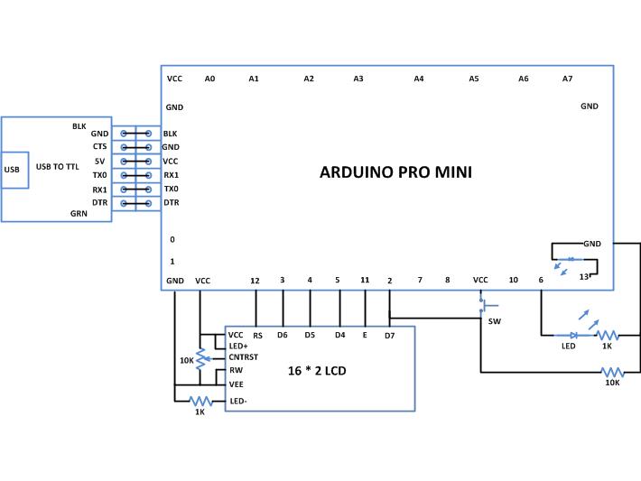
###


Circuit Diagrams

Circuit-Diagram-Making-A-Simple-Variable-Frequency-Generator-Using-Arduino

Project Components

  • Arduino Pro Mini
  • LCD
  • LED
  • Resistor

Project Video


Filed Under: Arduino Projects
Tagged With: Arduino, variable frequency generator
 

Next Article

← Previous Article
Next Article →

Questions related to this article?
👉Ask and discuss on EDAboard.com and Electro-Tech-Online.com forums.


Tell Us What You Think!! Cancel reply

You must be logged in to post a comment.

EE TECH TOOLBOX

“ee
Tech Toolbox: 5G Technology
This Tech Toolbox covers the basics of 5G technology plus a story about how engineers designed and built a prototype DSL router mostly from old cellphone parts. Download this first 5G/wired/wireless communications Tech Toolbox to learn more!

EE Learning Center

EE Learning Center
“engineers
EXPAND YOUR KNOWLEDGE AND STAY CONNECTED
Get the latest info on technologies, tools and strategies for EE professionals.

HAVE A QUESTION?

Have a technical question about an article or other engineering questions? Check out our engineering forums EDABoard.com and Electro-Tech-Online.com where you can get those questions asked and answered by your peers!


RSS EDABOARD.com Discussions

  • Inconsistent Charge Termination Voltage with battery charger
  • 21V keeps getting shorted to my UART line.
  • Voltage mode pushpull is a nonsense SMPS?
  • Voltage mode push pull with extra DC blocking capacitor
  • NXP library issue in awr

RSS Electro-Tech-Online.com Discussions

  • Is AI making embedded software developers more productive?
  • Why can't I breadboard this oscillator?
  • using a RTC in SF basic
  • Parts required for a personal project
  • Cataract Lens Options?

Featured – RPi Python Programming (27 Part)

  • RPi Python Programming 21: The SIM900A AT commands
  • RPi Python Programming 22: Calls & SMS using a SIM900A GSM-GPRS modem
  • RPi Python Programming 23: Interfacing a NEO-6MV2 GPS module with Raspberry Pi
  • RPi Python Programming 24: I2C explained
  • RPi Python Programming 25 – Synchronous serial communication in Raspberry Pi using I2C protocol
  • RPi Python Programming 26 – Interfacing ADXL345 accelerometer sensor with Raspberry Pi

Recent Articles

  • GigaDevice launches GD32C231 MCU series with 48MHz Cortex-M23 core and 64KB Flash
  • Advanced Energy releases 425 W CF-rated medical power supply in 3.5 x 6 x 1.5-inch format”
  • LEM combines shunt and Hall effect sensing in 2000 A current measurement unit
  • What is AWS IoT Core and when should you use it?
  • AC-DC power supply extends voltage range to 800 V DC

EE ENGINEERING TRAINING DAYS

engineering

Submit a Guest Post

submit a guest post
Engineers Garage
  • Analog IC TIps
  • Connector Tips
  • Battery Power Tips
  • DesignFast
  • EDABoard Forums
  • EE World Online
  • Electro-Tech-Online Forums
  • EV Engineering
  • Microcontroller Tips
  • Power Electronic Tips
  • Sensor Tips
  • Test and Measurement Tips
  • 5G Technology World
  • Subscribe to our newsletter
  • About Us
  • Contact Us
  • Advertise

Copyright © 2025 WTWH Media LLC. All Rights Reserved. The material on this site may not be reproduced, distributed, transmitted, cached or otherwise used, except with the prior written permission of WTWH Media
Privacy Policy

Search Engineers Garage

  • Electronic Projects & Tutorials
    • Electronic Projects
      • Arduino Projects
      • AVR
      • Raspberry pi
      • ESP8266
      • BeagleBone
      • 8051 Microcontroller
      • ARM
      • PIC Microcontroller
      • STM32
    • Tutorials
      • Audio Electronics
      • Battery Management
      • Brainwave
      • Electric Vehicles
      • EMI/EMC/RFI
      • Hardware Filters
      • IoT tutorials
      • Power Tutorials
      • Python
      • Sensors
      • USB
      • VHDL
    • Circuit Design
    • Project Videos
    • Components
  • Articles
    • Tech Articles
    • Insight
    • Invention Stories
    • How to
    • What Is
  • News
    • Electronic Product News
    • Business News
    • Company/Start-up News
    • DIY Reviews
    • Guest Post
  • Forums
    • EDABoard.com
    • Electro-Tech-Online
    • EG Forum Archive
  • DigiKey Store
    • Cables, Wires
    • Connectors, Interconnect
    • Discrete
    • Electromechanical
    • Embedded Computers
    • Enclosures, Hardware, Office
    • Integrated Circuits (ICs)
    • Isolators
    • LED/Optoelectronics
    • Passive
    • Power, Circuit Protection
    • Programmers
    • RF, Wireless
    • Semiconductors
    • Sensors, Transducers
    • Test Products
    • Tools
  • Learn
    • eBooks/Tech Tips
    • Design Guides
    • Learning Center
    • Tech Toolboxes
    • Webinars & Digital Events
  • Resources
    • Digital Issues
    • EE Training Days
    • LEAP Awards
    • Podcasts
    • Webinars / Digital Events
    • White Papers
    • Engineering Diversity & Inclusion
    • DesignFast
  • Guest Post Guidelines
  • Advertise
  • Subscribe