The Raspberry pi is a mini computer which is designed in a single board with all the essential components required for running an operating system. The Raspberry pi board runs on ARM11 processor but is available at extremely cheap price. The board is provided with a RCA connector which can be used to connect it directly to a TV screen which is based on PAL and NTSC standard. The board also has a HDMI connector output which can be used to connect the board to a HD TV.
The Raspberry pi is a device which uses the Broadcom controller chip which is a SoC (System on Chip). This SoC has the ARM11 processor which runs on 700 MHz at its core. This powerful processor and the controller having the peripherals like timers, interrupt controller, GPIO, PCM / I2S, DMA controller, I2C, SPI slave, PWM, UART, USB etc. Linux operating systems especially Ubuntu is preferred for all kind of programming and development. The operating systems like Archlinux ARM, OpenELEC, Pidora, Raspbmc, RISC OS and the Raspbian and also Ubuntu versions are available for the Raspberrypi board.
To access the peripherals of the Broadcom controller of the Raspberrypi board using C language, a C library is available called “bcm2835” which can be downloaded and installed on the Linux OS. This tutorial explains how to set a pin as input pin for the Raspberrypi board and how to read value of that pin with the help of the bcm2835 libarary.
[[wysiwyg_imageupload:10568:]]
In this project the Raspberrypi board is loaded with Ubuntu and is remotely accessed using VNC. The Raspberrypi board is also connected to the internet. There are 26 connectors which can be taken out from the connector port of the Raspberrypi board. All the connector pins are taken out using 13*2 pin female connectors and at the other end of their wire 26 pin Burg stick male connectors are attached. The Burg stick male connectors allow each pin out from the Raspberrypi board to be plugged into the holes of a breadboard. To access the pins that coming out of the Broadcom controller the C library “bcm2835” has been downloaded and installed.
Each pin of the Raspberrypi board is defined inside the header file <bcm2835.h> which can be included in the C code as:
#include <bcm2835.h>
The functions for accessing most of the peripherals including the General Purpose IO pins are also available in this header file. The pin out details of the raspberrypi board is given below:
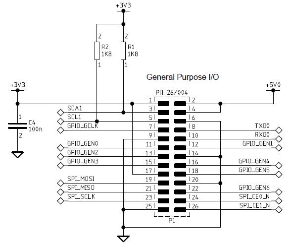
Fig. 2: General Purpose I/O pins of Raspberry Pi
|
PIN NUMBER |
DESCRIPTION |
|
1 |
3.3V |
|
2 |
5V |
|
3 |
SDA |
|
4 |
5V |
|
5 |
SCL |
|
6 |
GND |
|
7 |
SCK, GPIO_7 |
|
8 |
TX |
|
9 |
GND |
|
10 |
RX |
|
11 |
GPIO_0 |
|
12 |
GPIO_1 |
|
13 |
GPIO_2 |
|
14 |
GND |
|
15 |
GPIO_3 |
|
16 |
GPIO_4 |
|
17 |
3.3V |
|
18 |
GPIO_5 |
|
19 |
MOSI |
|
20 |
GND |
|
21 |
MISO |
|
22 |
GPIO_6 |
|
23 |
SCLK |
|
24 |
CS_1 |
|
25 |
GND |
|
26 |
CS_2 |
Fig. 3: Pin Out Details Of Raspberry Pi Board
The following section discusses how to write a C code for setting a GPIO pin as the input pin and how to read the value of that pin.
Few functions from the library <bcm2835.h> can be used here and the details of them are given below;
|
Function |
Description |
Parameters |
Return |
||
|
int bcm2835_init ( void ) |
initialize the library |
|
0 : failed |
||
|
1 : successful |
|||||
|
int bcm2835_close ( void ) |
Close the library |
|
0 : failed |
||
|
1 : successful |
|||||
|
void bcm2835_gpio_fsel ( uint8_t pin, uint8_t mode ) |
Sets the Function Select register for the given pin, which configures the pin as Input, Output or one of the 6 alternate functions. |
pin: GPIO number |
|
||
|
mode: Mode to set
|
|||||
|
Input |
BCM2835_GPIO_FSEL_INPT |
||||
|
Output |
BCM2835_GPIO_FSEL_OUTP |
||||
|
void bcm2835_gpio_set_pud ( uint8_t pin, uint8_t pud ) |
Sets the Pull-up/down mode for the specified pin |
pin: GPIO number |
|
||
|
pud: desired Pull-up/down mode |
|||||
|
disable pull-up/down |
BCM2835_GPIO_PUD_OFF |
||||
|
Pull Down |
BCM2835_GPIO_PUD_DOWN |
||||
|
Pull Up |
BCM2835_GPIO_PUD_UP |
||||
|
uint8_t bcm2835_gpio_lev ( uint8_t pin ) |
Reads the current level on the specified pin |
pin: GPIO number |
0: pin low |
|
|
1: pin high |
||||
|
void bcm2835_gpio_write ( uint8_t pin, uint8_t on ) |
Sets the output state of the specified pin |
pin: GPIO number |
|
|
|
on: state to be set |
||||
|
Set high |
HIGH |
|||
|
Set low |
LOW |
|||
|
void bcm2835_delay ( unsigned int millis ) |
Delays for the specified number of milliseconds |
millis: required elay in milliseconds |
|
|
Fig. 4: Functions From Library <bcm2835.h> For Setting A GPIO Pin As Input Pin
Using the above functions the following code sets a pin, the pin number 7 on the pins of the Raspberrypi board as an input pin. The code also continuously reads the value from that pin and writes the same value to another pin, pin number 15 which has been set as an output pin. The input pin is connected to push button and is pulled down using 1K resistors. The output pin is connected to the LEDs through another 1K resistor.
The function ‘bcm2835_gpio_fsel ()’ is used to set the pins as input and output and the function ‘bcm2835_gpio_set_pud ()’ is used to turn off the pull up/down from the pin. The function ‘bcm2835_gpio_lev ()’ is used to read the value of the pin and ‘bcm2835_gpio_write ()’ is used to write the value to the output pin.
Project Source Code
###
//------------------------------------------ input pin reading --------------------------------------------------// #include <bcm2835.h>#define IN_PIN RPI_GPIO_P1_07
#define OUT_PIN RPI_GPIO_P1_15int main ( void )
{
char value;if ( ! bcm2835_init () )
return 1;// Set RPI pin P1-07 to be an input
bcm2835_gpio_fsel ( IN_PIN, BCM2835_GPIO_FSEL_INPT );
// with a pullup
bcm2835_gpio_set_pud ( IN_PIN, BCM2835_GPIO_PUD_OFF );bcm2835_gpio_fsel ( OUT_PIN, BCM2835_GPIO_FSEL_OUTP );
while ( 1 )
{
// Read value of input pin
value = bcm2835_gpio_lev ( IN_PIN );
// Write the value to the output pin
bcm2835_gpio_write ( OUT_PIN, value );
delay ( 100 );
}
bcm2835_close ();
return 0;
}//------------------------------------------ input pin reading --------------------------------------------------//
###
Circuit Diagrams

Project Components
Project Video
Filed Under: Raspberry pi
Filed Under: Raspberry pi

Questions related to this article?
👉Ask and discuss on EDAboard.com and Electro-Tech-Online.com forums.
Tell Us What You Think!!
You must be logged in to post a comment.