Increasing RF transmission range by increasing transmission power and antenna size
Background:
Now we know that RF transmission range can be increased by increasing transmission power and antenna size. If we apply only one, we will not get enough range. So, better way is to apply both increasing in transmission power and antenna size to get longer range.
Description:
In this project we are connecting antenna with sufficient length as per our calculations, and applying input power in variable manner to get required range.
With these techniques we can get more range compare to previous two methods.
Required components and other equipments:
Sr. no. Name of component Required qut
1 RF Tx module(434Mhz) 1
2 RF Rx module(434Mhz) 1
3 HT12E 1
4 HT12D 1
5 LED 5
6 Resistor – 1KΩ (Quarter watt) 8
7 Resistor – 1MΩ (Quarter watt) 1
8 Resistor – 50KΩ (Quarter watt) 1
9 Pushbutton 4
11 Battery – 9V 2
15 Bread board 2
18 connecting wires —
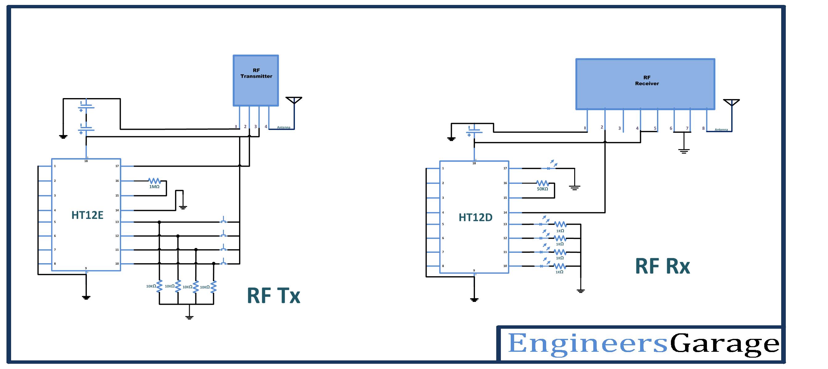
Circuit diagram:
Pictures:


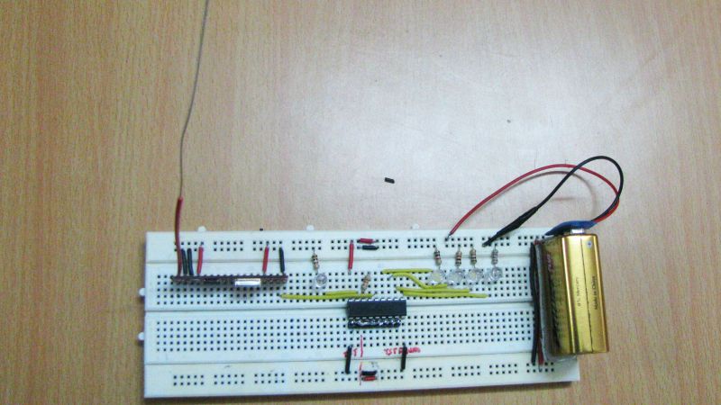
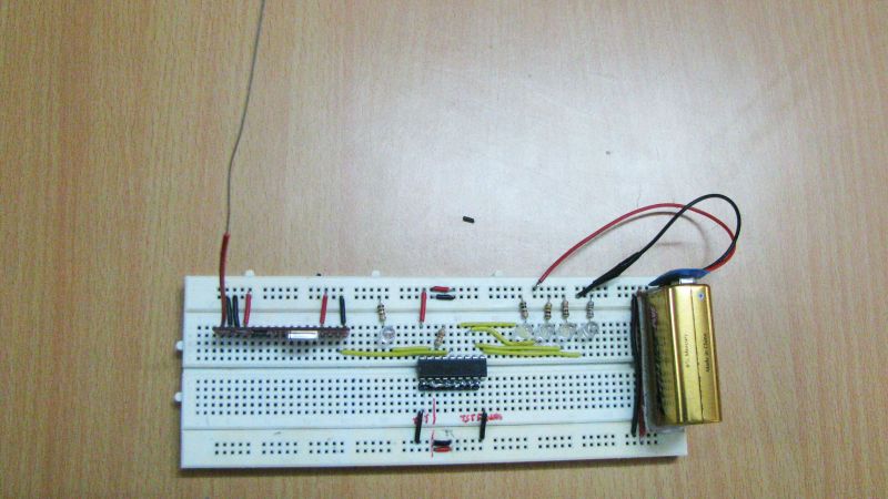

Description:
Procedure:
Transmitter section:
Step1: connect the four push buttons to the data input pins (10, 11, 12, 13) of HT12E, with pull down resistors of 1 K.
Step2: connect 1MΩ resistor between 15 and 16 pins of HT12E.
Step3: connect 17 pin to the 2nd pin of RF transmitter, and 14 pin connect to the ground.
Step4: 1-8 pins of HT12E are address pins, connect all to the ground. And connect pin 18 to Vcc and pin 9 to ground.
Step5: Connect RF Tx module’s pin 1 to the ground, pin 3 to the Vcc and pin 4 to the antenna.
Step6: connect two 9V batteries to increase power.
Step7: calculate the antenna size using antenna theory, and connect at pin 4 of Tx module
Receiver section:
Step1: connect four LED’s to the output pins (10, 11, 12, 13) of HT12D, with pull down resistors.
Step2: connect 50KΩ resistor between 15 and 16 pins of HT12D.
Step3: connect pin 14 of HT12D to the 2nd pin of RF transmitter. Connect pin 17 to the LED indicator (it will glow when signal is received)
Step4: pins 1-8 of HT12D are address pins, connect all to the ground. Connect pin 18 to Vcc and pin 9 to ground.
Step5: Connect RF Rx module’s 1, 6, 7 pins to the ground, pins 4 & 5 to the Vcc and pin 8 to the antenna.
Step6: calculate the antenna size using antenna theory, and connect at 8th pin of Rx module
Now let us look at the operation of circuit
Working:
1. When any switch is pressed at encoder input pin, the encoder generates a data sequence at 14th pin that is fed to the 2nd pin of Tx module. Tx module transmits signal as ASK modulated signal with data in amplitude variations. At receiver side, received signal is given to the pin 14 of decoder chip, from pin 2 of Rx module. As a output, respective Led will glow at decoder output pins
2. The circuit is tested with following 4 different configurations
a. Constant power supply without antenna (9V)
b. Constant power supply with antenna (9V + antenna)
c. Variable power supply without antenna (two 9V batteries in parallel)
d. Variable power supply with antenna (two 9V batteries in parallel + antenna)
3. For each different configuration note down the readings for transmission range. Compare the reading. The range should be high in the case of the Variable power supply with antenna (two 9V batteries in parallel + antenna).
4. In this experiment we can realize that, the range can be increase by increasing power or antenna and we can get longer range by increasing power and antenna size both simultaneously.
a. Constant power supply without antenna(9V)
68m
b. Constant power supply with antenna(9V + antenna)
150m
c. Variable power supply without antenna (two 9V batteries in parallel)
100m
d. Variable power supply with antenna (two 9V batteries in parallel + antenna)
300m
Antenna size calculations:
The frequency of the RF carrier is = 434 Mhz.
Frequency = cycles/sec
= 434 M/sec
Time period = 1/ frequency
= 1/434×106
= 2.3 nsec
Speed of light (c) = 3×10 m/sec
Then,
Wavelength = speed / frequency.
= speed × time period
= 2.3 nsec × 3×10⁸ m/sec
= 0.69 m
As per antenna theory antenna size should be half or quarter size of the wavelength.
So
Quarter wavelength = 0.69 m/4
= 17.25cm.
Precautions:
1. Address lines should be same at both transmitter and receiver side.
2. At transmitter 14th pin of HT12E should be connect to ground or connect a switch between ground and the 14th pin to reset the encoder.
3. At transmitter side resistor between 15 and 16 pins of HT12E should be between 750MΩ to 1MΩ and at receiver side resistor between 15 and 16 pins of HT12D should be between 30KΩ to 50KΩ.
4. Incase if you want to use any other battery please check the data sheets of HT12E/HT12D before.

Project Source Code
Project Source Code
###

//Program to
Circuit Diagrams
Filed Under: Electronic Projects

Questions related to this article?
👉Ask and discuss on Electro-Tech-Online.com and EDAboard.com forums.
Tell Us What You Think!!
You must be logged in to post a comment.