In today’s world most of the electronic appliances needs DC voltages from 3-12 Volts for operation. An adaptor is a device which is used to convert high AC voltages to low DC voltage. Adaptors come in various shapes, sizes & configuration depending on the use. In some cases adaptors are used to provide power to electronic appliances like video games, modems etc and in some cases they are used to charge the primary battery of the electronic device and also act as alternate power source like mobile chargers, laptop chargers, cell chargers etc. A typical adaptor is shown in the figure below.
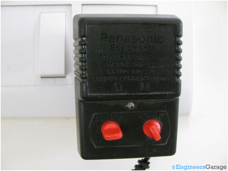
The left red knob changes the output voltage while the right one is used to change the polarity of output voltage.
An adaptor works in these 3 simple steps:
1. AC voltage is stepped down using a Transformer
2. A rectifier circuit changes the AC signal to DC signal.
3. A capacitor filters the signal to smooth DC waveform.
Internal Circuitry
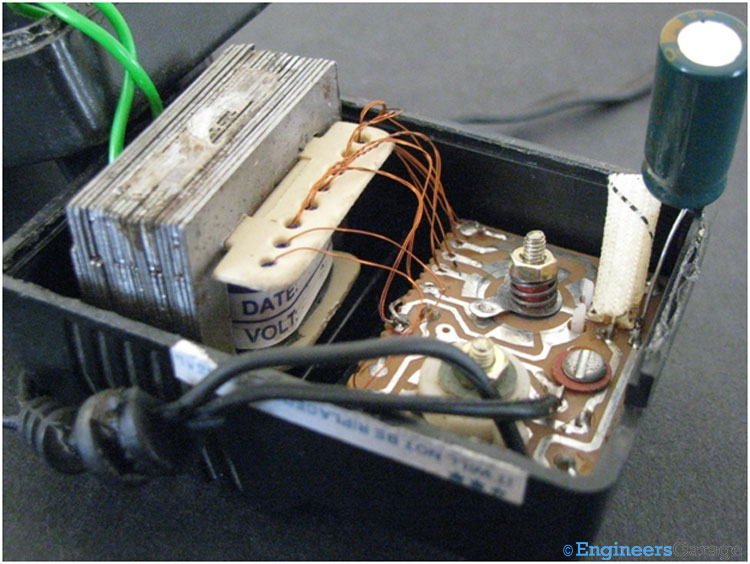
On removing the outer plastic body of the adaptor, glimpse of transformer and other circuitry is shown in the image above.
Connections to transformer & Voltage Regulator Knob
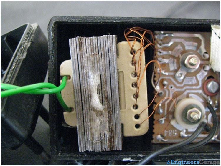
In above image, you can see a clear picture of how transformer is fitted into the adaptor. The two green color wires takes input from the AC supply and are connected to the primary winding of the transformer. The copper wires on the right side are the output wires of transformer coming out of the secondary winding and connected to the rectifier circuit. You can see there are a number of output wires on the secondary side which corresponds to the different output DC voltage.
Voltage Regulator Knob
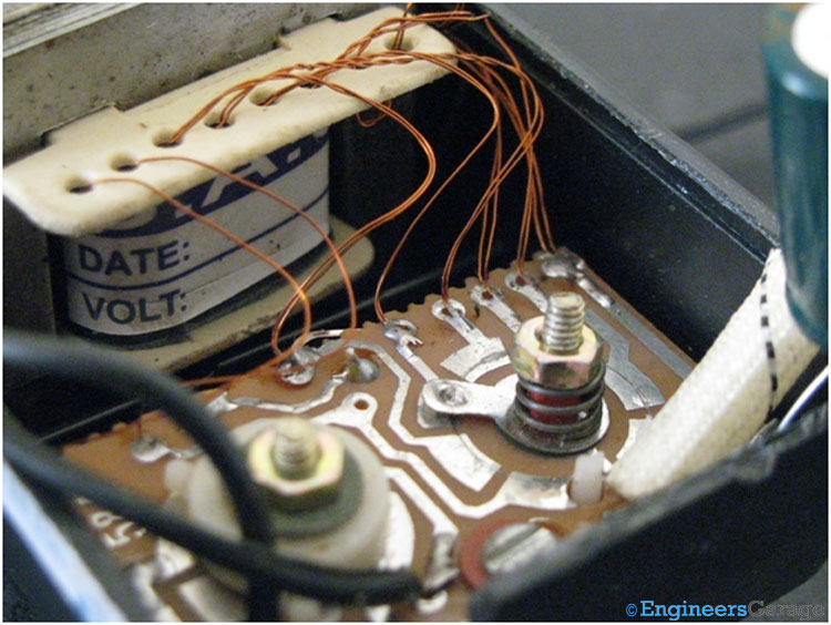
The above image shows the plate attached with the voltage regulator knob which connect the plate with different output wire. While we rotate the knob, the plate moves accordingly and connects with different output wires.
Rectifier Circuit & Filter Capacitor
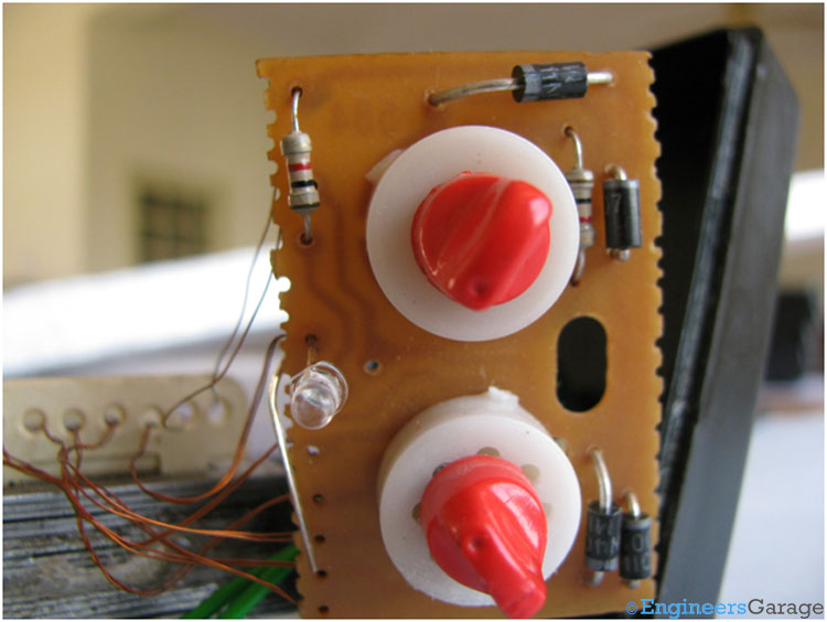
The above image shows the full wave rectifier circuit with four diodes mounted on the PCB which converts the AC signal to DC signal.
Filter Capacitor
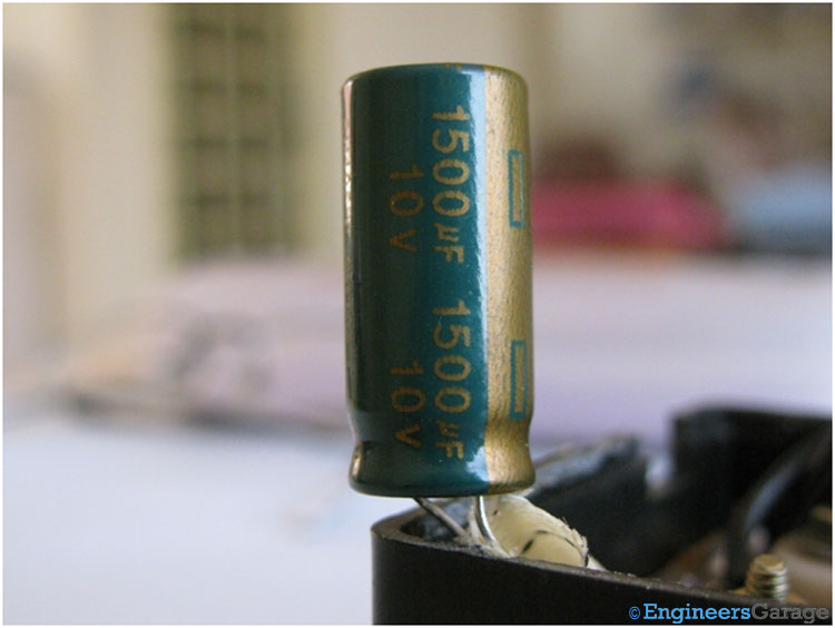
The capacitor is connected in the circuit to filter the ripples from output DC voltage.
Transformer

Working: AC adaptor works by having a transformer, a rectifying circuit and a capacitor to filter the signal. Input AC signal directly enters in the primary coil of the transformer. Transformer steps down the input AC voltage and gives low AC voltage as output from the secondary coils. The different numbers of output coils are used to provide different AC output voltages. A selector switch is used to select which output of transformer secondary must be connected to rectifier circuit. For example in order to take 6V DC output from the adaptor the secondary coil of transformer which provides 6V AC as output is connected to the input of rectifier circuit. Finally a capacitor attached with the rectifier circuit removes the AC ripples to give a smooth DC output.
Filed Under: Insight


Questions related to this article?
👉Ask and discuss on Electro-Tech-Online.com and EDAboard.com forums.
Tell Us What You Think!!
You must be logged in to post a comment.