Belling-Lee connectors are one of the oldest types of coaxial connectors and are still widely used in many countries across the world. Commonly known as PAL connectors or TV aerial plugs, these connectors have been named after the company which designed them Belling and Lee Ltd. Apart from television, these RF connectors are used in radio sets too: why? Easy wiring and installation.
This 2 wired coaxial cable connector is available in various modifications- different casings, plating over the connecting nib etc. Even in terms of sizes there are two types: standard and miniature. The structure of these connectors is quite similar to the conventional RF connectors but they have an extra insulation over the tip where the connectors interface with the device. Let’s learn more about the Belling-Lee connector and their internal structure in this Insight.
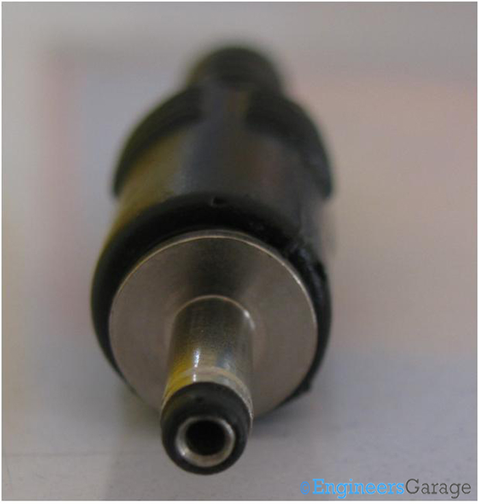
Fig. 1: Connecting interface of Belling Lee Connector
Connecting Interface: Image 01 shows the connecting interface region of a standard male Belling-Lee connector. Casted out of steel, the connector has a small hole in the center through which it is inserted into the port of the connecting device. A black layer of insulator surrounds the connecting region which separates the pin from the alloy structure of the connector.
Plastic Cover & Wire Terminal
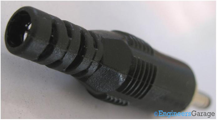
Fig. 2: Plastic Cover of Connector
Cover: A plastic covering insulates the region where the wires join to the connector.
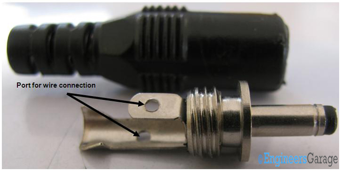
Fig. 3: Wire Terminals of Belling-Lee Connector
Wire Terminal: Belling-Lee connector has been designed for 2 wired coaxial cables. Out of the two wires, one carries data, and connects to the data pin. The other wire serves as a reference and is grounded in the insulator.
Wire Placement & Connecting Pin
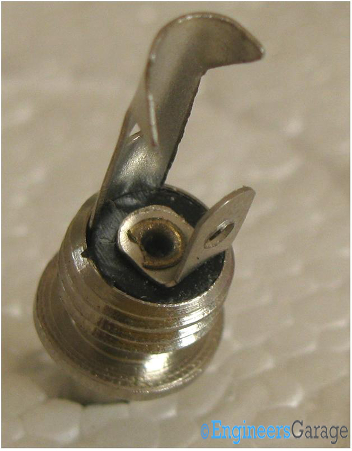
Fig. 4: Wire Terminals and Wire Arrangement Mechanism of Belling-Lee Connector
Terminal Placement: Image 04 details the way in which wire terminals are placed. The placing keeps the wires distant from each other irrespective of the orientation of the connector.
The terminal which connects to signal wire is punched in order to link to the output. The terminal connecting to the reference signal gets placed inside the insulator.
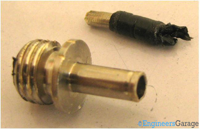
Fig. 5: Internals of Connecting Pin
Connecting pin: When the wire terminals are removed, the connecting pin is plucked out. It is tightly sheathed by a rubber sleeve which prevents signal leakage. Placed inside a hollow cylindrical structure of the connector, it is covered with a rubber layer. Only a little part of the connecting pin emerges out which the user sees as an insulating strip near the tip.
Filed Under: Insight


Questions related to this article?
👉Ask and discuss on Electro-Tech-Online.com and EDAboard.com forums.
Tell Us What You Think!!
You must be logged in to post a comment.